YS12调整.pdf - 第38页
Service Engineer Service I nformati on SI080 4004 E-000 = YS12 , YG12: Procedure for adjustmen t after installa tion of the mach ine 38/60 6. If “A MF i ndex” falls bel ow 1.0.w hen performing accuracy check by A CP If t…

Service Engineer
Service Information
SI0804004E-000 = YS12, YG12: Procedure for adjustment after installation of the machine
37/60
When the measured result of “AMF index 1” is 1.0 or above;
As it indicates that the mounting accuracy is within specification, adjustment does not need to
be performed.
However, it is recommended to perform feedback of the compensation value to increase the
accuracy.
Fill in the Index value after adjustment as “The data after feedback” on the check sheet.
Move on to the next process:
- If the machine is equipped with the multi camera: Move on to “0.7. Accuracy adjustment of the
multi camera (Option)’.
- If the machine is not equipped with the multi camera: Move on to “8. Items to be adjusted
relating to the mounting accuracy of the machine”
When the measured result of “AMF index 1” falls below 1.0.
If the result falls below “1.0”, the lowest Index value of each head is indicated by boldface.
Please perform adjustment referring to the next section “6. If “AMF index” falls below
1.0.when performing accuracy check by ACP”.
Service Engineer
Service Information
SI0804004E-000 = YS12, YG12: Procedure for adjustment after installation of the machine
38/60
6. If “AMF index” falls below 1.0.when performing accuracy
check by ACP
If the measured results of “AMF index 1” and “AMF index 2” fall below 1.0, analyze the measured
data by “VgChart” and check the mounting state. If the mounting is unstable, the AMF index
cannot be improved no matter how many times the adjustment by ACP is performed.
Please check the cause of the problem referring to the analysis result, and perform adjustment
again.
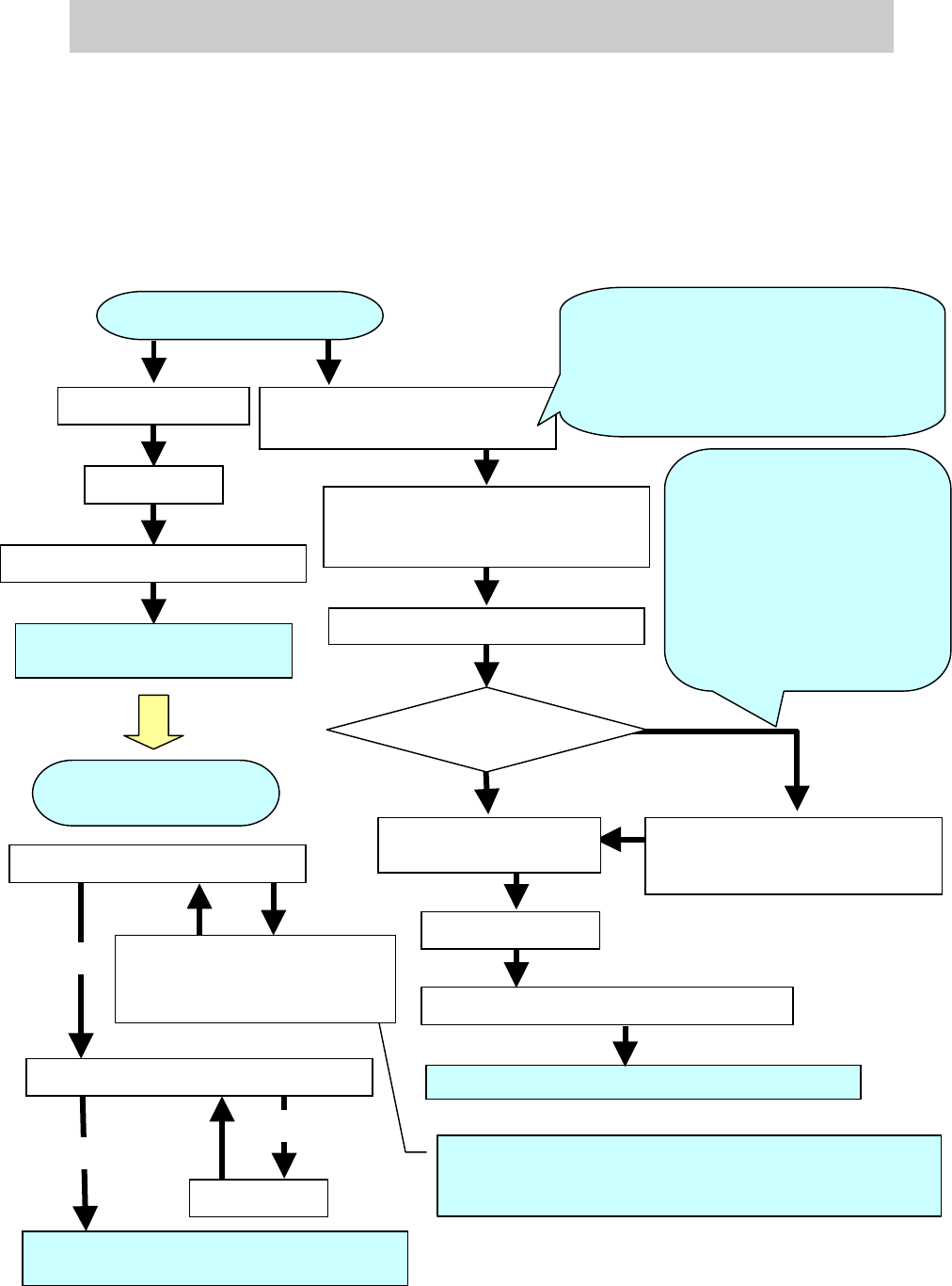
6.1. The workflow when “AMF Index” falls below 1.000
Figure 52
Check the “VgChart”
ACP adjustment of the Scan camera
X
Y
offset deviation
OK
If the mounting results data
spreads in the X and Y directions
Save the result of mounting
accuracy after adjustment
Feedback
-
Scale adjustment of the fiducial camer
a
- Scale adjustment of the scan camera
- Positioning of the scan camera
Feedback
- Scale adjustment of the multi
camera
- Positioning of the multi camera
Save the result of mounting accuracy after adjustment
ACP adjustment of the multi
camera
FAMF adjustment of the multi camera
When performing the head
offset adjustment in the
mounting adjustment of the
main scan camera, please
make sure to perform scale
adjustment and positioning of
the multi camera. Please
perform scale adjustment and
positioning of the multi camera
after performing Head offset
adjustment of the scan camera.
Adjustment of the multi
camera (Option)
NG
Feedback
When the AMF Index value falls below 1.0, the initial
adjustments of the items adjusted for the main camera (Fiducial
camera scale, Head offset) are not basically performed.
The value of “Index 2” varies depends on
the patterns of the mounting results data. If
the value is 1.0 or above, please perform
feedback for the correction value instead of
performing adjustments such as scale
adjustment.
Multi camera
(Option) Equipped?
ACP adjustment of the
Scan camera
Accuracy check of the Scan camera by ACP
- Scale adjustment of the multi
camera
- Positioning of the multi camera
NG
OK
Save the result of mounting accuracy after
adjustment
Adjustment of Head offset XY
YES
NO
Service Engineer
Service Information
SI0804004E-000 = YS12, YG12: Procedure for adjustment after installation of the machine
39/60
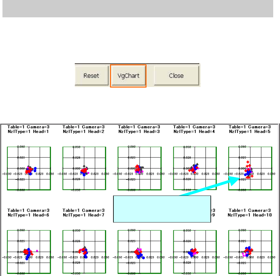
Double click on the graph to
display the details.
6.2. Check the “VgChart”
1. Click on the [VgChart] button.
The chart screen is automatically created based on the measured data by clicking on the
[VgChart] button.
Figure 53
2. Check the Chart screen
Check the Chart screen to determine which head is the causal factor that the “AMF Index 1”
does not meet the specified value.
Figure 54
Analyze the chart and perform further adjustment if needed.