YS12调整.pdf - 第51页
Service Engineer Service I nformati on SI080 4004 E-000 = YS12 , YG12: Procedure for adjustmen t after installa tion of the mach ine 51/60 7.4. Check the result of the measurement 7.4.1. Check the value of t he “Index (T…
Service Engineer
Service Information
SI0804004E-000 = YS12, YG12: Procedure for adjustment after installation of the machine
50/60
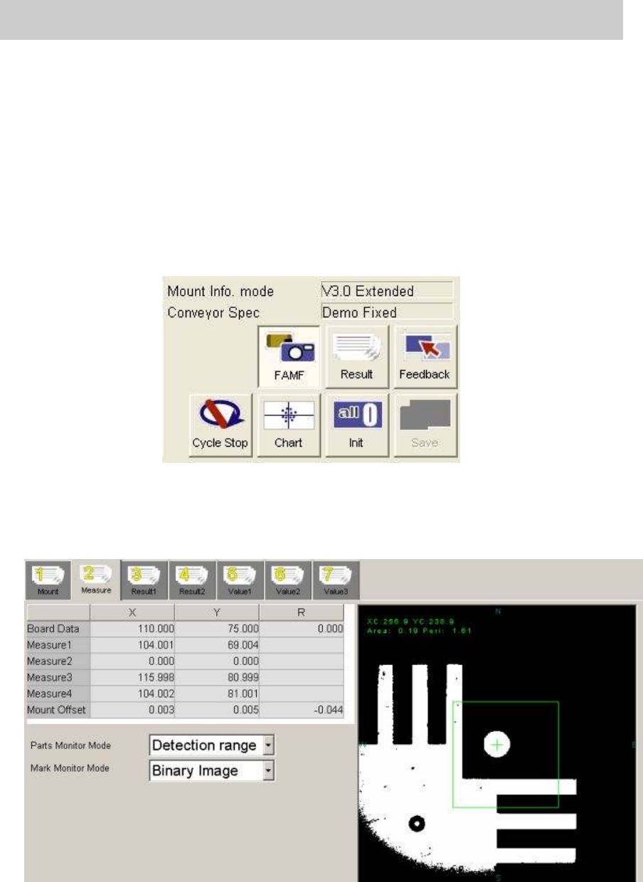
7.3.7. Start operation and measurement
1. Click on the [FAMF] button.
Without clicking on the button, the function to check the mounting state does not work.
2. Click on the [Init] button before starting operation.
Click on the [Init] button for initialization just in case the previous measurement data still
remains.
3. Click on the [Cycle Stop] button.
As “Demo Fixed” is selected from “Conveyor Spec”,
without clicking on the button, the
mounting operation will be repeated again and again.
Figure 70
4. Click on the [Start] button on the machine to start operation.
* The recognition result of the each mounting can be checked on the “Measure 2” tab.
Please keep an eye on the value of the “Mount Offset” during operation.
Figure 71
Service Engineer
Service Information
SI0804004E-000 = YS12, YG12: Procedure for adjustment after installation of the machine
51/60
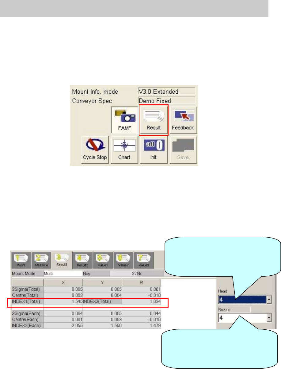
7.4. Check the result of the measurement
7.4.1. Check the value of the “Index (Total)”
1. Click on the [Result] button after completing measurement.
The value of the “Index” can be checked on the “Result 1” tab.
Figure 72
2. Display “Result 1” screen to check the values in the “INDEX 1 (Total)” and “INDEX2 (Total)”
fields.
Select the nozzle type used for mounting from the dropdown list at the lower right.
When the 304A nozzle is used: 4
When the 315A nozzle is used: 5
Please fill in the value as “The data before feedback” on the check sheet.
Figure 73
Select the relevant head from the
dropdown list to check the value of
the “INDEX 2” for each head on the
“Result 1” screen.
Select the relevant nozzle from the
dropdown list to check the total
values of the “INDEX 1” and
“INDEX 2” on the “Result 1” screen.
Service Engineer
Service Information
SI0804004E-000 = YS12, YG12: Procedure for adjustment after installation of the machine
52/60
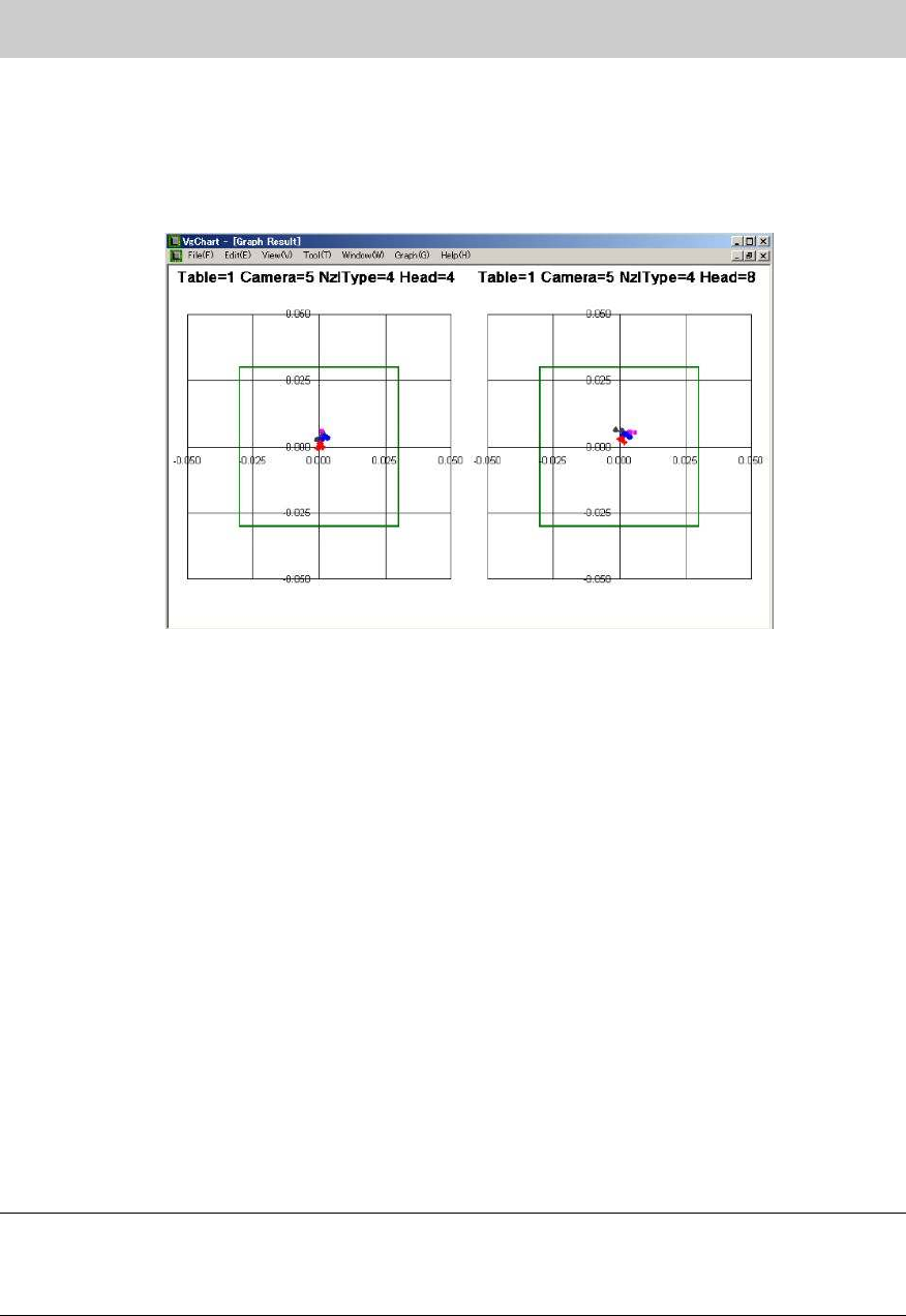
3. Click on the [Chart] button.
Click on the [Chart] button to display the “VgChart” screen for checking the accuracy.
Please check the result on the “VgChart” screen regardless of the values in the “INDEX 1
(Total)” and “INDEX2 (Total)”
Figure 74
Please refer to “6. If “AMF index” falls below 1.0.when performing accuracy check by ACP” for
how to interpret the graphs.
7.4.2. When the value of INDEX (Total) is 1.000 or above
1. Check the INDEX (Total)
If the values in the “INDEX 1 (Total)” and “INDEX2 (Total)” on the “Result 1” tab are 1.000 or
above, the adjustment does not need to be performed.
Please fill in the value as “The data after feedback” on the check sheet.
2. Initialize the data.
After recording the values of “INDEX” on the check sheet, click on the [Init] button to initialize
the measurement data.
3. Save “RESULT.DAT”.
Change the name of the “RESULT.DAT” file in the “D:¥Machine¥Result” on the Explorer.
Please add the serial number of the machine, date the adjustment is performed, and the head
number to the file name.
Create a folder using the date of adjustment as a name in “D:¥Machine¥Result” and save the
data in the folder.
Note:
Even though the value of INDEX is 1.000 or above, if any deviation is found on the chart, please
perform feedback of the correction value.
Please refer to “7.4.3. When the value of INDEX (Total) falls below 1.000” for the method.