YS12调整.pdf - 第54页
Service Engineer Service I nformati on SI080 4004 E-000 = YS12 , YG12: Procedure for adjustmen t after installa tion of the mach ine 54/60 8. Items to be adjusted relating to the mounting accuracy of the machine 8.1.How …
Service Engineer
Service Information
SI0804004E-000 = YS12, YG12: Procedure for adjustment after installation of the machine
53/60
7.4.3. When the value of INDEX (Total) falls below 1.000
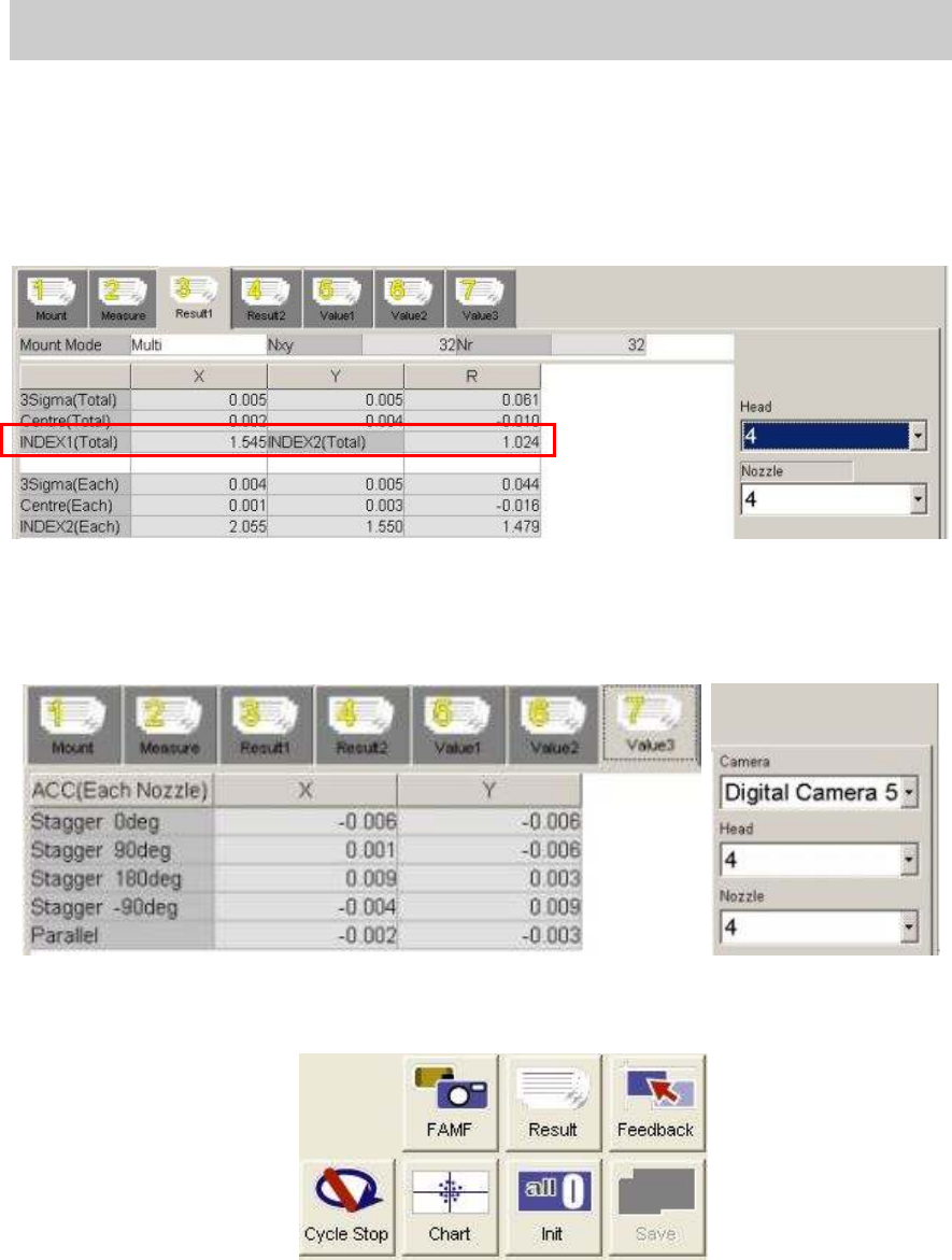
1. Check the values of “INDEX (Total)”
Display the “Result 1” and check the values in the “INDEX 1 (Total)” and “INDEX2 (Total)”. If
the values fall below 1.000, the fields turn red and the lowest Index value of each head is
indicated by boldface. Please check the recognition state and the cause of the problem on the
“VgChart” screen and perform adjustment.
Figure 75
2. Click on the [Feedback] button to check the compensation value.
If you click on the [Feedback] value, the compensation values are automatically calculated.
Please display the “Value 1”, the “Value 2”and the “Value 3” tabs to check if any abnormal
values are found in the compensation value fields.
3. Click on the [Save] button.
After checking the compensation values, click on the [Save] button to save the values in the
system data
. When the data is saved, the “Result” data is initialized.
Figure 76
4. Check the accuracy by performing mounting with FAMF.
When performing feedback of the compensation value and readjustment, please delete the
“RESULT.DAT” file before start mounting. Otherwise, the data is added to the previous data.
5. Check the accuracy.
Please refer to “7.4.2. When the value of INDEX (Total) is 1.000 or above” for the procedure
after checking the accuracy (when the value of the INDEX is 1.000 or above.).
Please fill in the value as “The data after feedback” in the relevant column of the check
sheet.
Service Engineer
Service Information
SI0804004E-000 = YS12, YG12: Procedure for adjustment after installation of the machine
54/60
8. Items to be adjusted relating to the mounting accuracy of the
machine
8.1.How to perform scale adjustment of the fiducial camera
Adjust the camera scale by using the marks on the board as the conventional method.
When the machine is equipped with the sub fiducial camera (Option), perform adjustment for
the both fiducial cameras. Table 25 shows the specified values.
Items to be adjusted Specified value
Scale XY 10.000 - 10.600
Camera Angle 0.000 +- 0.500 degrees
Table 25
Click on the [Fiducial Camera] button on the main screen of the CalibSm.
Select “Scale” from the “Adjust Item” on the “Fiducial Camera” screen.
Perform adjustment by using the Φ0.5mm mark on the glass board.
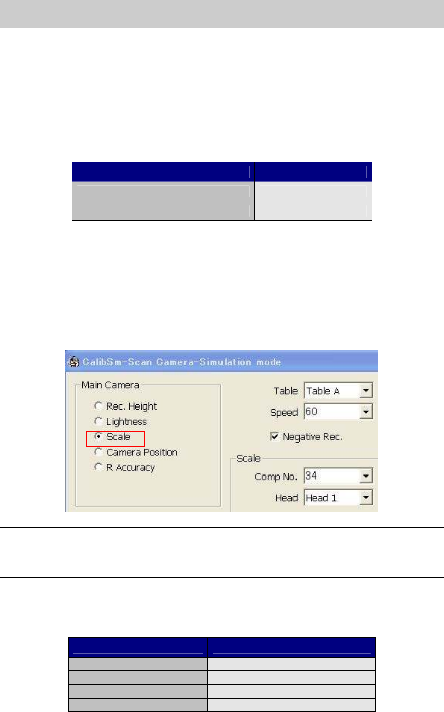
8.2.How to perform scale adjustment of the scan camera
Click on the [Scan Camera] button on the main screen of the CalibSm.
Select “Scale” from the “Main Camera” item on the “Scan Camera” screen.
Figure 77
Note:
As the scan camera is not equipped with the coaxial light, perform adjustment by using the Glass
QFP with the white sticker on the back to recognize the leads as black leads.
Please make sure that the “Negative Rec.” item is ticked.
- Nozzle to be used: Type 303A (314A) nozzle (For SOP)
- Component to be used: Glass QFP 16pin (with white sticker) (KHY-M880A-00)
- Part No.: No.34 QFP16_P0.8_WHITE (Board data: MCH_SETUP)
Items to be adjusted Specified value
Angle
0.000 + - 0.100
Scale X
24.000+ - 0.100
Scale Y
24.000 + - 0.100
Offset
0.000 + - 0.050
Table 26
Service Engineer
Service Information
SI0804004E-000 = YS12, YG12: Procedure for adjustment after installation of the machine
55/60
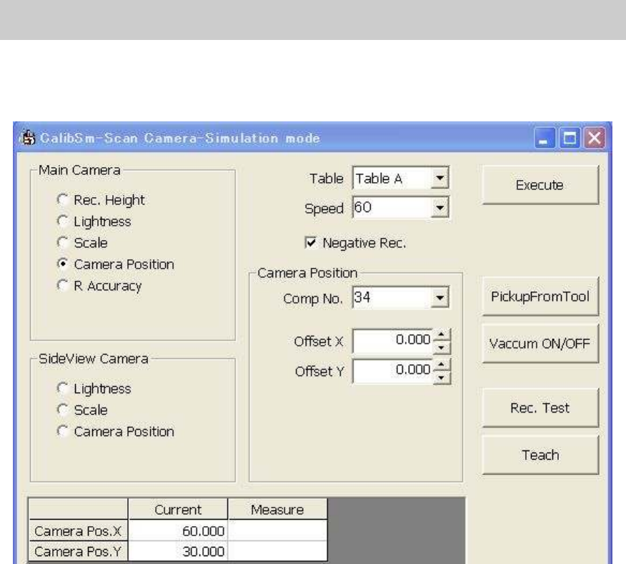
8.3. Positioning of the Scan Camera (Main camera)
Click on the [Scan Camera] button on the main screen of the CalibSm.
Select “Camera Position” from the “Main Camera” item on the “Scan Camera” screen.
Figure 78
Please follow the same procedure as the scale adjustment of the scan camera.
There should not be much difference between the measured value and the current value.
8.4. How to adjust “Head Offset XY”
The adjustment of the Head Offset XY is performed with the main camera (Scan camera).
(It is also possible to perform adjustment with the multi camera by logging in as “Engineer”.)
[Tools required for adjustment]
- Nozzle to be used: Type 303A (314A) nozzle (For SOP)
- Component to be used: Glass QFP 16pin (with white sticker) (KHY-M880A-00)
- Part No.: No.34 QFP16_P0.8_WHITE (Board data: MCH_SETUP)
[Procedure for adjustment]
Click on the [Head Offset] button on the main screen of the CalibSm.
Select “Head Offset XY” from the “Adjust Item”.
Make the nozzle vacuum the Glass QFP 16pin (with white sticker on the back) to perform
adjustment.
The number of the head to be adjusted at the same time is limited depends how many Glass
QFPs are prepared.
Please tick only the boxes with the names of the head to be adjusted before adjustment. Untick the
boxes after adjustment, and then tick the rest of the boxes to perform the next round of
adjustment.