YS12调整.pdf - 第58页
Service Engineer Service I nformati on SI080 4004 E-000 = YS12 , YG12: Procedure for adjustmen t after installa tion of the mach ine 58/60 9. Items to be checked af ter accuracy adjustment 9.1.Check if the board is trans…
Service Engineer
Service Information
SI0804004E-000 = YS12, YG12: Procedure for adjustment after installation of the machine
57/60
When the machine is equipped with only one multi camera, whichever side the camera is mounted,
it is Digital camera 5.
Make the nozzle vacuum the Glass QFP and perform adjustment.
- Nozzle to be used: Type 304A (315A) nozzle (For QFP)
- Component to be used: Glass QFP 68pin (KW8-M880A-10* GLASS QFP 68P)
- Part No.:No.11 QFP68_P0.65 (Board data: MCH_SETUP)
Items to be adjusted Specified value
Angle 0.000 +- 0.100
Scale X 24.000 +- 0.100
Scale Y 24.000 +- 0.100
Offset 0.000 +- 0.050
Table 29
8.7. Positioning of the Multi Camera
Click on the [Multi Camera] button on the main screen of the CalibSm.
Select “Camera Pos.” from the “Adjust Item” on the “Multi Camera” screen.
- Nozzle to be used: Type 304A (315A) nozzle (For QFP)
- Component to be used: Glass QFP 68pin (KW8-M880A-10* GLASS QFP 68P)
- Part No.: No.11 QFP68_P0.65 (Board data: MCH_SETUP)
8.8. Check the machine reference
Click on the [Axis] button on the main screen of the CalibSm.
Click on the [Originize] button on the “Axis” screen to perform ”Return to origin”.
If the values do not meet the specification, please investigate the cause of the problem and take
relevant measures.
Axis name Specification (%)
XY 50 +- 5
Z 10 +- 5
R 45 +- 2
W 50 +- 5
PU 50 +- 5
SC 62 +- 5
Table 30
If the values do not fall within specification, click on the [Originize] button again in order to check if
the reference values are stable.
Repeatability of the reference: Within +-2%
Service Engineer
Service Information
SI0804004E-000 = YS12, YG12: Procedure for adjustment after installation of the machine
58/60
9. Items to be checked after accuracy adjustment
9.1.Check if the board is transferred properly from the upstream machine to the
downstream machine
1. Output request signal to the upstream machine, and check the signal sent from the
downstream machine on the “I/O” tab on the “Unit” screen,
2. Change the setting of the “Conveyor Spec” to “Line”.
Click on the [Edit] button on the “Sequence” tab on the “Board” screen, and then select “Skip”
from the “Mount item” in order to transfer a board from the upstream machine to the
downstream machine.
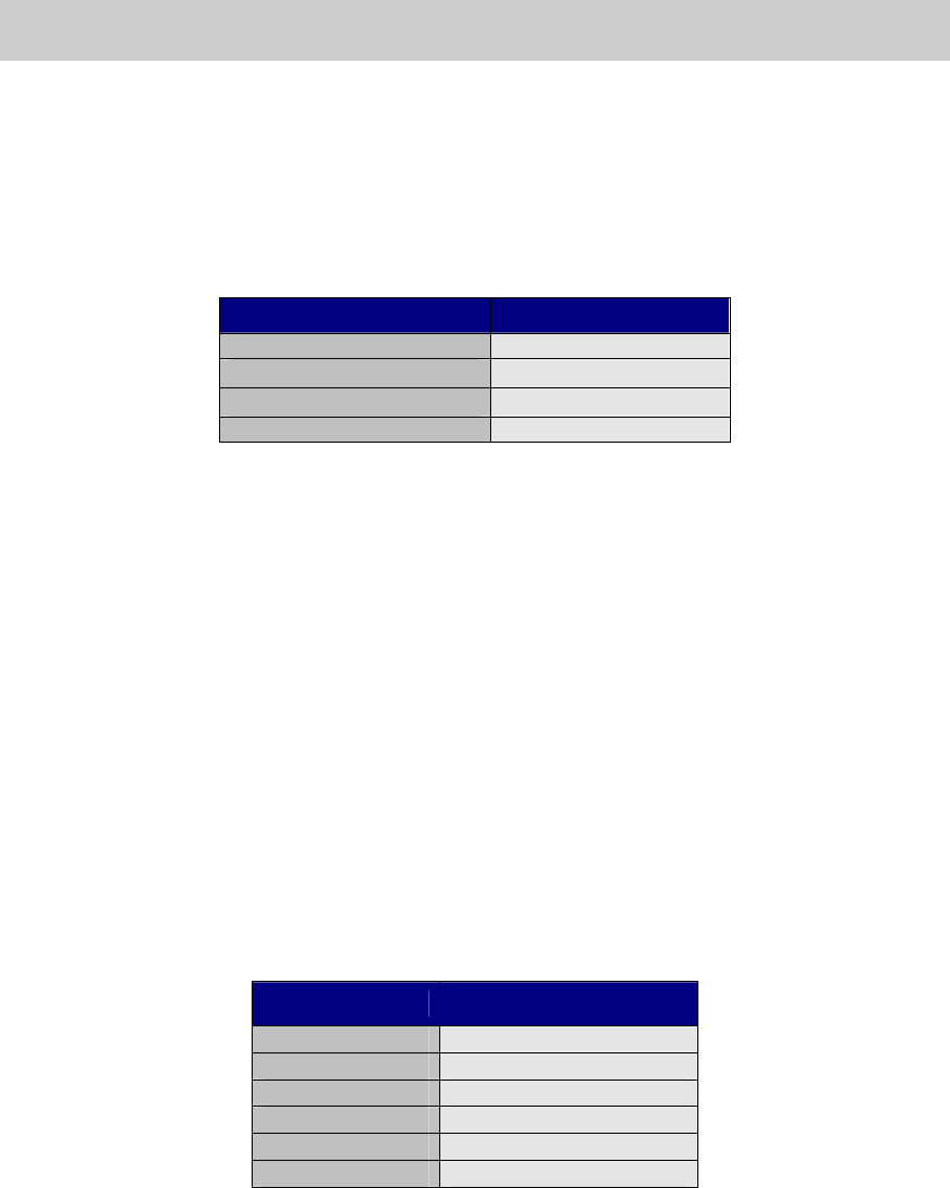
9.2.Check the pickup position of the feeder
Click on the [FeederPos] button on the main screen of the CalibSm and check the pickup
position of the feeder.
Figure 80
Input the compensation value
(Offset value) of the tool to be
used before adjustment.
Service Engineer
Service Information
SI0804004E-000 = YS12, YG12: Procedure for adjustment after installation of the machine
59/60
9.3. Check the operation of the blow station
Click on the [Cleaning Blow] button on the “Head” tab on the “Unit” screen to check the
operation of the blow station.
Figure 81
9.4. Check the “PCB origin”
1. Set a board on the mounting position.
Set the coordinate of the PCB origin XY to 0.00 and move the camera to the position.
2. Click on the [Position] button on the main screen of the CalibSm and check the values of the
“Edge Clamp”.
9.5. Check the operation of the “Nozzle change” function (Option)
1. Click on the [Nozzle Change] buttons on the “Head” tab on the “Unit” screen to check the
operation of the “Nozzle Check” function.
2. Click on the [ANC] button on the main screen of the CalibSm, and select “Test Change
Nozzle” to check the adjustment result.
Figure 82
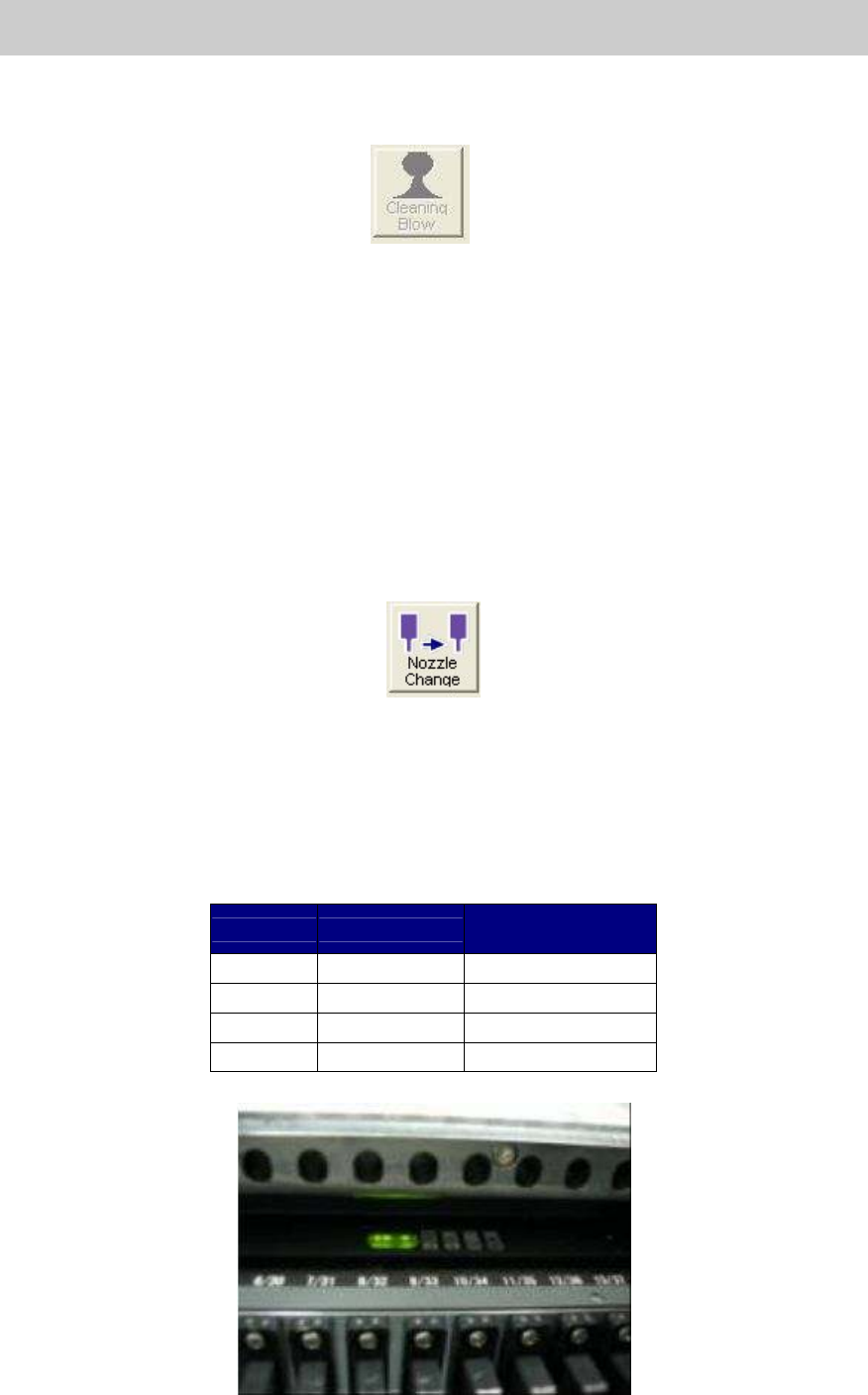
9.6. Check the operation of the feeder exchange carriage (Option)
1. Check if all the carriage can be installed into the machine or be released from the machine
without hitch.
2. Check if the LED of the carriage lights up when the carriage is fully installed into the correct
position of the machine.
Indication
LED
Normal lighting
condition
+24V Green LED Lights up
+5V Green LED Lights up
SC Orange LED Blinks (1 sec.)
MON Green LED Lights up
Table 31
Figure 83