LmrXP142机械手册.pdf - 第124页
Part 5 Chapter 1 Servo System Troubleshooting Edition 3.0 5-1-25 XP-142E Mechanical Reference AC Servopack Check List for Troubleshooting Alarm Alarm Name Status Cause Remedy A.CC0 Multi-turn Limit Disagreement • Occurre…
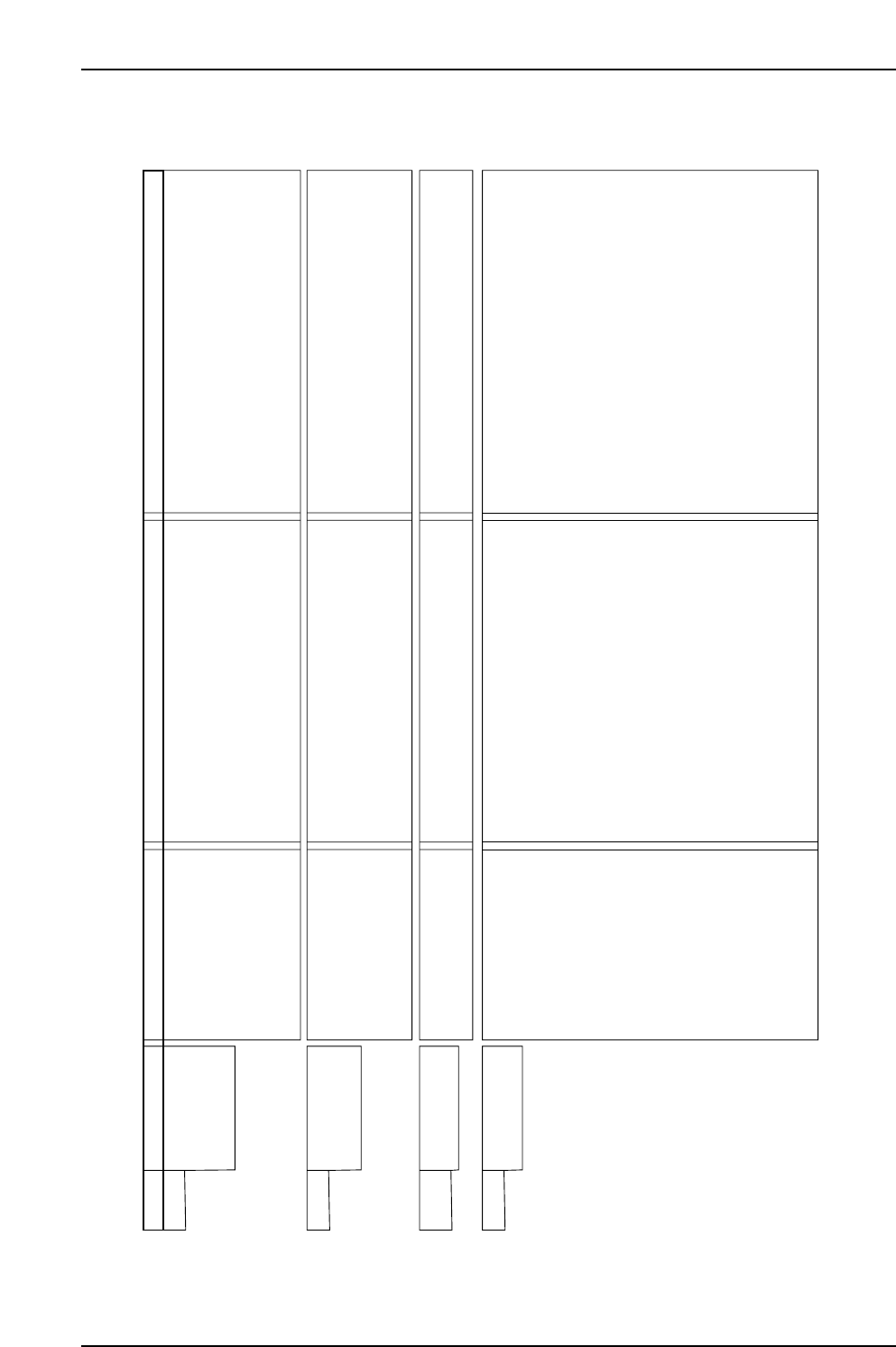
Part 5 Chapter 1 Servo System Troubleshooting
Edition 3.0 5-1-24 XP-142E Mechanical Reference
AC Servopack Check List for Troubleshooting
Alarm Alarm Name Status Cause Remedy
A.C91 Encoder
Communications
Position Data
Error
• Occurred when the control
power supply was turned
ON or during operation.
• The noise interference occurred on the signal
line because the encoder cable is bent and
the sheath is damaged.
• The encoder cable is bundled with a
high-current line or near a high-current line.
• The FG varies because of the influence from
machines on the servomotor side, such as
welder.
• Correct the encoder cable layout.
• Correct the encoder cable layout so that no surge
is applied.
• Make the grounding for the machine separately
from PG side FG.
A.C92 Encoder
Communications
Timer Error
• Occurred when the control
power supply was turned
ON or during operation.
• Noise interference occurred on the signal line
from the encoder.
• Excessive vibration and shocks were applied
to the encoder.
• An encoder fault occurred.
• A SERVOPACK board fault occurred.
• Take a measure against noise for the encoder
wiring.
• Reduce the machine vibration or mount the
servomotor securely.
• Replace the servomotor.
• Replace the SERVOPACK.
A.CA0 Encoder
Parameter Error
• Occurred when the control
power supply was turned
ON.
• An encoder fault occurred.
• A SERVOPACK board fault occurred.
• Replace the servomotor.
• Replace the SERVOPACK.
A.Cb0 Encoder
Echoback Error
• Occurred when the control
power supply was turned
ON or during operation.
• The encoder wiring and contact are incorrect.
• Noise interference occurred due to incorrect
encoder cable specifications.
• Noise interference occurred because the
wiring distance for the encoder cable is too
Iong.
• Noise interference occurred on the signal line,
because the encoder cable is bent and the
sheath is damaged.
• The encoder cable is bundled with a
high-current line or near a high-current line.
• The FG varies because of the influence from
the servomotor side machines, such as welder.
• Noise interference occurred on the signal line
from the encoder.
• Excessive vibration and shocks to the
encoder was applied.
• An encoder fault occurred.
• A SERVOPACK board fault occurred.
• Correct the encoder wiring.
• Use tinned annealed copper twisted-pair or
twisted-pair shielded wire with a core of at least
0.12 mm (0.002 in ).
• The wiring distance must be 20m (65.6 ft) max.
• Correct the encoder cable layout.
• Correct the encoder cable layout so that no surge
is applied.
• Ground the machine separately from PG side FG.
• Take measures against noise for the encoder
wiring.
• Reduce the machine vibration or mount the
servomotor securely.
• Replace the servomotor.
• Replace the SERVOPACK.
NP1MT021E
22
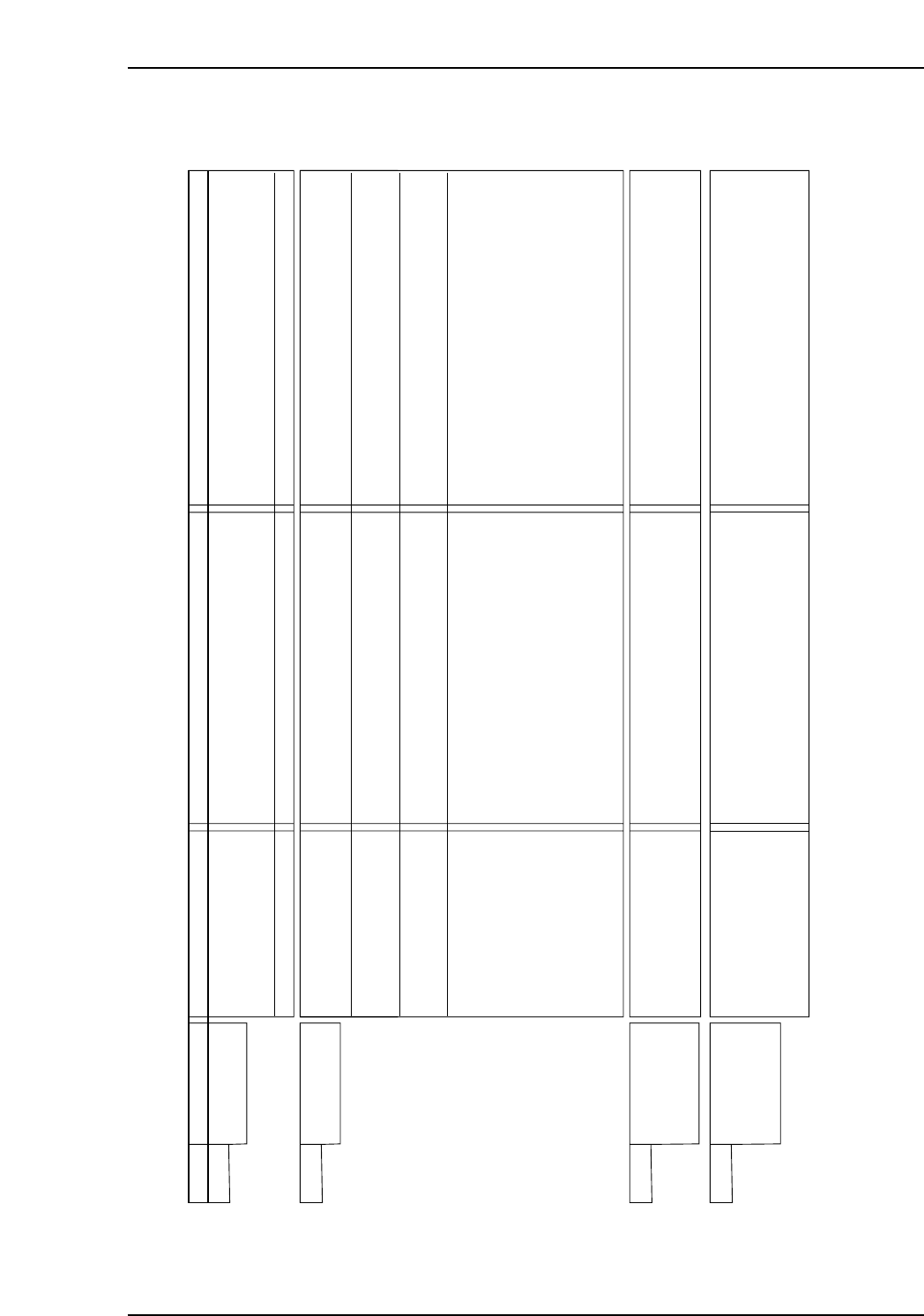
Part 5 Chapter 1 Servo System Troubleshooting
Edition 3.0 5-1-25 XP-142E Mechanical Reference
AC Servopack Check List for Troubleshooting
Alarm Alarm Name Status Cause Remedy
A.CC0 Multi-turn Limit
Disagreement
• Occurred when the control
power supply was turned
ON.
• Occurred during operation.
• The parameter settings for the SERVOPACK
are incorrect.
• The multiturn limit value for the encoder is not
set or was changed.
• A SERVOPACK board fault occurred.
• Correct the setting of Pn205 (0 to 65535).
• Execute Fn013 at the occurrence of alarm.
• Replace the SERVOPACK.
A.d00 Position Error
Pulse Overflow
• Occurred when the control
power supply was turned
ON.
• Occurred at the
servomotor high-speed
operation.
• The servomotor did not
run with position reference
input.
• Normal movement, but
occurred with a long
distance reference input.
• A SERVOPACK board fault occurred.
• The contact in the servomotor U, V, and W
wirings is faulty.
• A SERVOPACK board fault occurred.
• Wirings of the servomotor U. V. and W are
incorrect.
• A SERVOPACK board fault occurred.
• The SERVOPACK gain adjustment is
improper.
• The position reference pulse frequency is too
high.
• Setting of the parameter Pn520 (Position
Error Pulse Overflow Alarm Level) is incorrect.
• The servomotor specifications do not meet
the load conditions such as torque and
moment of inertia.
• Replace the SERVOPACK.
• Correct the servomotor wiring.
• Correct the encoder wiring.
• Replace the SERVOPACK.
• Correct the servomotor wiring.
• Replace the SERVOPACK.
• Increase the speed loop gain (Pn100) and
position loop gain (Pn102).
• Adjust slowly the position reference pulse
frequency.
• Apply the smoothing function.
• Correct the electronic gear ratio.
• Set the parameter Pn520 to proper value.
• Reconsider and correct the load and servomotor
capacity.
A.d01 Position Error
Pulse Overflow
Alarm at Servo
ON
• Occurred when the control
power supply was turned
ON.
• Excessive position errors accumulated while
the servo is OFF
• With the setting not to clear the errors while
the servo is OFF, the servomotor was running.
• Do not run the servomotor in servo OFF status.
• Make the setting so that the errors are cleared
while the servo is OFF.
• Adjust the detection level.
A.d02 Position Error
Pulse Overflow
Alarm by Speed
Limit at Servo ON
• Occurred when the
servomotor was running.
• The servo turned ON with accumulated errors,
and reference pulse was input during
operation at the speed limit, therefore, the
errors exceeded the Position Error Pulse
Overflow Alarm Level (Pn520).
• Do not run the servomotor in servo OFF status.
• Make the setting so that the errors are cleared
while the servo is OFF.
• Correct the detection level.
• Adjust the speed limit level (Pn529) when servo
turns ON.
NP1MT022E
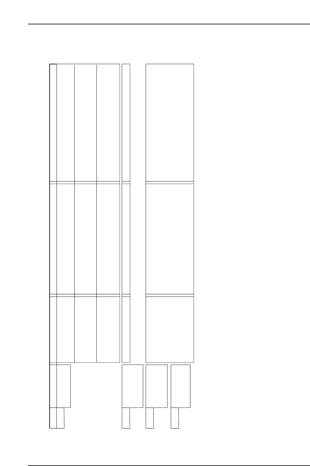
Part 5 Chapter 1 Servo System Troubleshooting
Edition 3.0 5-1-26 XP-142E Mechanical Reference
AC Servopack Check List for Troubleshooting
Alarm Alarm Name Status Cause Remedy
A.F10 Power Line
Open Phase
• Occurred when the control
power supply was turned
ON.
• Occurred when the main
circuit power supply was
turned ON.
• Occurred when the
servomotor was running.
• A SERVOPACK fault occurred.
• The three-phase power supply wiring is
incorrect.
• The three-phase power supply is unbalanced.
• A SERVOPACK fault occurred.
• The contact in three-phase power supply
wiring is faulty.
• Three-phase power supply is unbalanced.
• A SERVOPACK fault occurred.
• Replace the SERVOPACK.
• Correct the power supply wiring.
• Balance the power supply by changing phases.
• Replace the SERVOPACK.
• Correct the power supply wiring.
• Balance the power supply.
• Replace the SERVOPACK.
A.F20 Motor Discon-
nected or Current
Error
• Occurred during operation. • The servomotor cable is disconnected. • Correct the servomotor wiring.
CPF00 Digital Operator
Transmission
Error 1
• Occurred when the power
supply was turned ON
with digital operator
connected or when
connecting digital operator
with the power supply was
turned ON.
* 1: This alarm occurs when the communications is still disabled five seconds after digital operator power supply is ON, or when digital operator
communications disabled status stays while an option unit is connected.
* 2: This alarm occurs when digital operator received data error occurs consecutively five times, or when the state that digital operator receives no data
from SERVOPACK for one second or more occurs consecutively three times.
*1
*2
• The contact between the digital operator and
the SERVOPACK is faulty.
• The external noise interference occurred to
the digital operator or cable is faulty.
(The digital operator cable is near noise
source)
• A digital operator fault occurred.
• A SERVOPACK fault occurred.
• Insert securely the connector, or replace the
cable.
• Do not lay the cable near noise source.
• Install digital operator far from noise source.
• Replace the digital operator.
• Replace the SERVOPACK.
CPF01 Digital Operator
Transmission
Error 2
NP1MT023E