LmrXP142机械手册.pdf - 第127页
Part 5 Chapter 1 Servo System Troubleshooting Edition 3.0 5-1-28 XP-142E Mechanical Reference Warning Display and Troubleshooting Warning Warning Name Status Cause Remedy A.911 Vibration • Occurred during normal operatio…
Part 5 Chapter 1 Servo System Troubleshooting
Edition 3.0 5-1-27 XP-142E Mechanical Reference
Warning Display and Troubleshooting
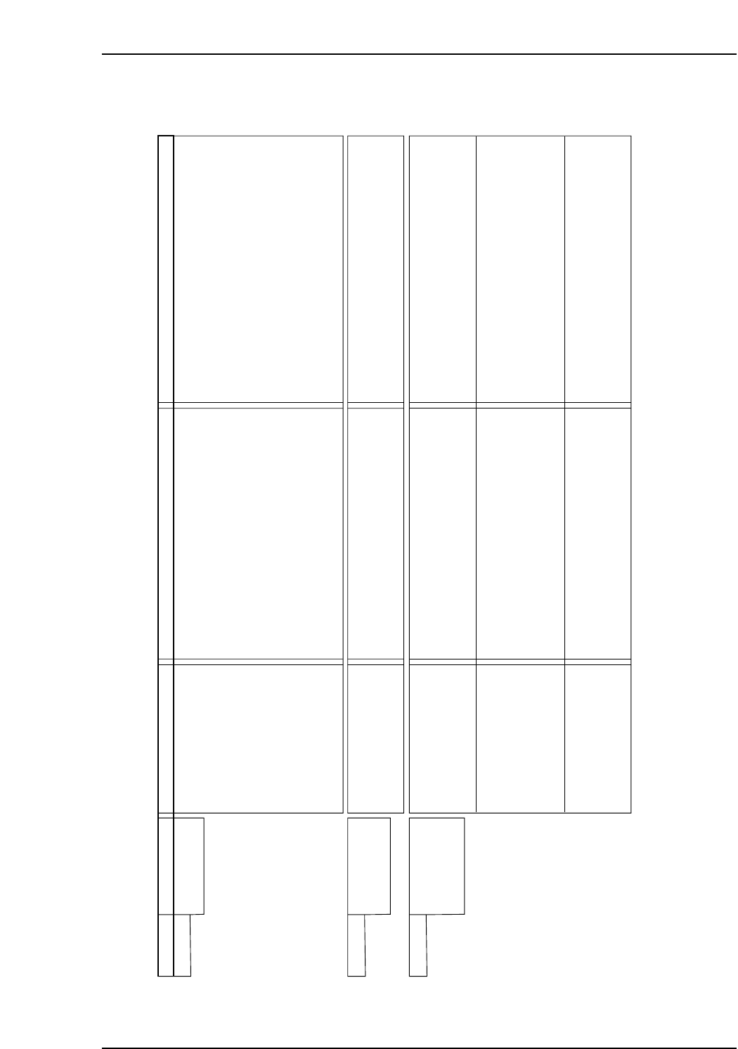
Warning Warnng Name Status Cause Remedy
A.900 Position Error
Pulse Overflow
• Occurred during operation. • A SERVOPACK board fault occurred.
• Wiring is incorrect or the contact of
servomotor U, V, and W is faulty.
• The SERVOPACK gain adjustment is
improper.
• The position reference pulse frequency is too
high.
• Setting of the parameter Pn520 (Position
Error Pulse Alarm Level) is improper.
• The servomotor specifications do not meet
the load conditions (torque, moment of inertia)
• Replace the SERVOPACK.
• Correct the servomotor wiring.
• Correct the encoder wiring.
• Increase the speed loop gain (Pn100) and
position loop gain (Pn102).
• Decrease slowly the position reference pulse
frequency.
• Apply the smoothing function.
• Adjust the electronic gear ratio.
• Set the parameter Pn520 to a value other than
"0".
• Reconsider and correct the load and servomotor
capacity.
A.901 Position Error
Pulse Overflow at
Servo ON
• Occurs when the servo
was ON.
• Errors accumulated excessively in servo OFF
status
• With the setting not to clear the errors while
the servo is OFF, the servomotor was running.
• Do not run the servomotor in servo OFF status.
• Make the setting so that the errors are cleared in
servo OFF status.
• Adjust the detection level.
A.910 Overload :
Warning for the
alarms A710 and
A720
• Occurs when the servo
was ON.
• The servomotor did not
run with a reference input.
• Occurred during operation.
• Wiring is incorrect and the contact in
servomotor wiring is faulty.
• Wiring is incorrect and the contact in encoder
wiring is faulty.
• A SERVOPACK fault occurred.
• Servomotor wiring is incorrect and the contact
is faulty.
• Encoder wiring is incorrect and the contact is
faulty.
• The starting torque exceeds the maximum
torque.
• A SERVOPACK fault occurred.
• The effective torque exceeds the rated torque.
• Temperature in the SERVOPACK panel is
high.
• A SERVOPACK fault occurred.
• Correct the servomotor wiring.
• Correct the encoder wiring.
• Replace the SERVOPACK.
• Correct the servomotor wiring.
• Correct the encoder wiring.
• Reconsider the load and operation conditions.
Or, check the servomotor capacity.
• Replace the SERVOPACK.
• Reconsider the load and operation conditions.
Or, check the servomotor capacity.
• Reduce the in-panel temperature to 55°C or less.
• Replace the SERVOPACK.
NP1MT024E
Part 5 Chapter 1 Servo System Troubleshooting
Edition 3.0 5-1-28 XP-142E Mechanical Reference
Warning Display and Troubleshooting
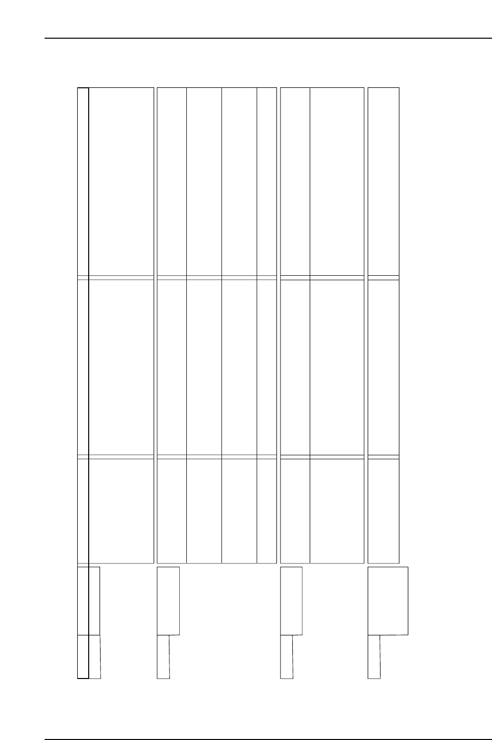
Warning Warning Name Status Cause Remedy
A.911 Vibration • Occurred during normal
operation.
• Servo Amplifier gain is improper.
• The moment of inertia ratio (Pn103) is greater
than the actual value, or fluctuates excessively.
• To adjust the gain, decrease the speed loop gain
(Pn100) and position loop gain (Pn101), and
increase the filter time constants such as torque
reference filter (Pn401).
• Change the moment of inertia ratio (Pn103)
to an appropriate value.
A.920 Regenerative
Overload
• Occurred when the control
power supply was turned
ON.
• Occurred during normal
operation (Large increase
of regenerative resistor
temperature.)
• Occurred during normal
operation (Small increase
of regenerative resistor
temperature).
• Occurred at servomotor
deceleration.
• A SERVOPACK fault occurred.
• Regenerative energy is excessive.
• Regenerative status continues.
• The setting of parameter Pn600 is smaller
than the external regenerative resistor
capacity.
• A SERVOPACK fault occurred.
• Regenerative energy is excessive.
• Replace the SERVOPACK.
• Check the regenerative resistor capacity, or
reconsider the load and operation conditions.
• Correct the setting of parameter Pn600.
• Replace the SERVOPACK.
• Check the regenerative resistor capacity, or
reconsider the load and operation conditions.
A.930 Absolute Encoder
Battery Warning
• Occurred when the control
power supply was turned
ON. (Setting: Pn002.2=1)
• Occurred 4 seconds or
more after the control
power supply was turned
ON. (Setting: Pn002.2=0)
When an absolute encoder
was used.
• A SERVOPACK board fault occurred. (The
absolute encoder is used in the incremental
encoder setting.)
• The battery connection is incorrect or faulty.
• The battery voltage is lower than the specified
value 2.7V.
• A SERVOPACK board fault occurred.
• Replace the SERVOPACK.
• Connect correctly the battery.
• Replace the battery, and turn OFF the encoder
power supply and ON again.
• Replace the SERVOPACK.
NP1MT025E
A.941 Change of
Parameters
Requires the
Setting Validation
• Occurred after having
changed parameter
setting.
• To validate new setting of this parameter, turn
OFF the power and ON again.
• Turn OFF the power and ON again.

Part 6 Setup
1. Leveling the Machine . . . . . . . . . . . . . . . . .6-1-1
2. Connecting the Air . . . . . . . . . . . . . . . . . . .6-2-1
3. Electrical Power Supply & Transformer Wiring
. . . . . . . . . . . . . . . . . . . . . . . . . . . . . . . . . .6-3-1
4. Connecting the Data Transmission Cable
<RS-232C> . . . . . . . . . . . . . . . . . . . . . . . .6-4-1
5. Connecting the Data Transmission Cable
<Ethernet> . . . . . . . . . . . . . . . . . . . . . . . . .6-5-1
6. Connecting the Panel Loading Interface and
Panel Request Signal Connectors . . . . . . .6-6-1
This section describes preparatory
procedures from machine
installation to test operation.