LmrXP142机械手册.pdf - 第32页
1. Machine Components Machine Front (Side 1) Machine Rear (Side 2) Transformer box Vacuum gauge Pressure gauge Air inlet Servo box 2 Operation panel 2 Safety cover 2 Hour meter XP1MN202E EMERGENCY STOP button Main switch…

Part 1
The Machine
1. Machine Components . . . . . . . . . . . . . . . .1-1-1
2. Functions of Each Component . . . . . . . . .1-2-1
This section explains the system
hardware, and contains information
about the machine and its
components.
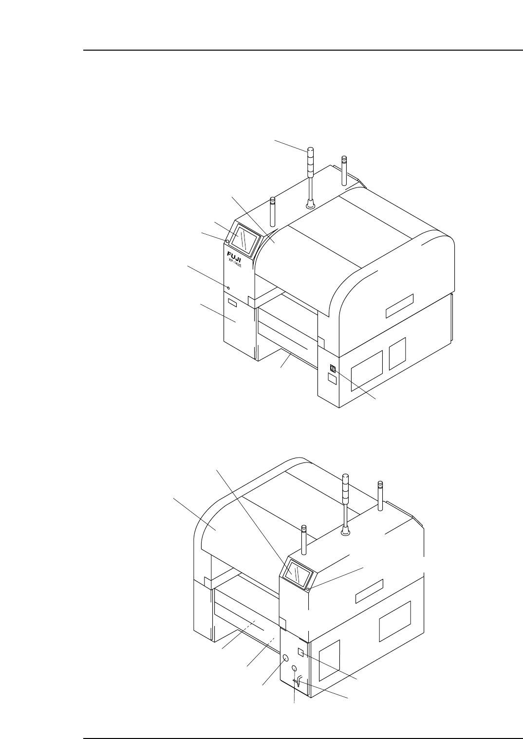
1. Machine Components
Machine Front (Side 1)
Machine Rear (Side 2)
Transformer box
Vacuum gauge
Pressure gauge
Air inlet
Servo box 2
Operation panel 2
Safety cover 2
Hour meter
XP1MN202E
EMERGENCY STOP button
Main switch
Servo box 1
Control box
Operation panel 1
EMERGENCY
STOP button
Safety switch
test button
Safety cover 1
Signal tower
XP1MN201Ea
Part 1 Chapter 1 Machine Components
Edition 3.0 1-1-1 XP-142E Mechanical Reference
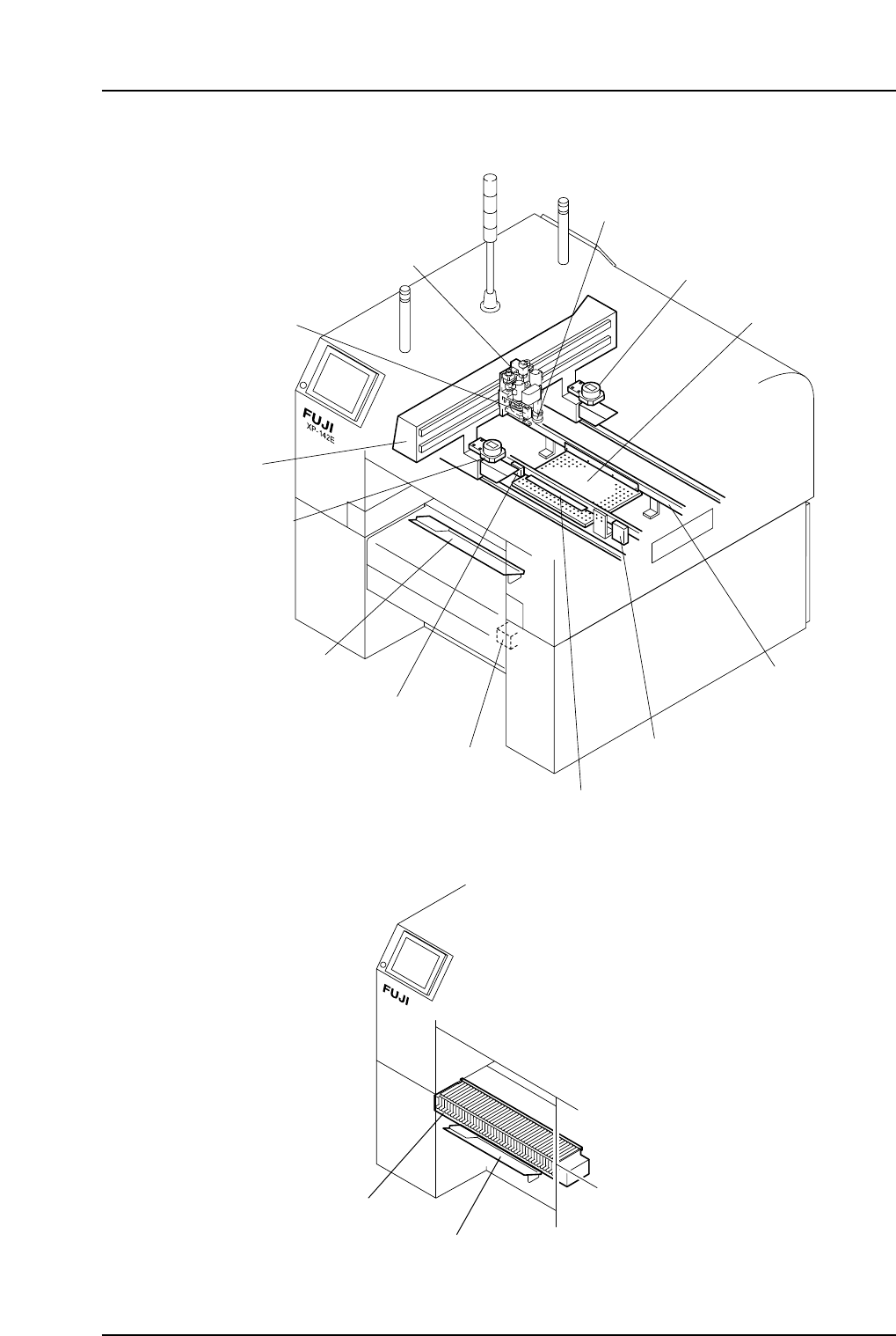
Machine Interior
<For Machines Equipped with a Fixed Device Table on Side 1>
Waste tape cutter
(option)
Fixed device table
XP1MN204E
Small parts reject box
Gauge chip parts
Panel lifter
Waste tape cutter
(Option)
Mark camera
Parts camera
Strobe light 1
Strobe light 2
Conveyor
Placing head
XY-robot
XP1MN203Ea
Strobe power
Medium size parts reject tray
Part 1 Chapter 1 Machine Components
Edition 3.0 1-1-2 XP-142E Mechanical Reference