LmrXP142机械手册.pdf - 第42页
Notes: Part 2 Chapter 2 Changing the Position of the Back-up Pins Edition 3.0 2-2-2 XP-142E Mechanical Reference
2. Changing the Position of the Back-up Pins
Point
Change the position of the back-up pins (vacuum or solid) to support a panel during
production. For panels where upward warping is a problem, vacuum back-up pins
should be used to maintain the flatness of the mounting surface.
Procedure
1. Lower the panel lifter if it is raised.
2. Adjust the conveyor width to the maximum width.
3. Remove the MFU from the machine.
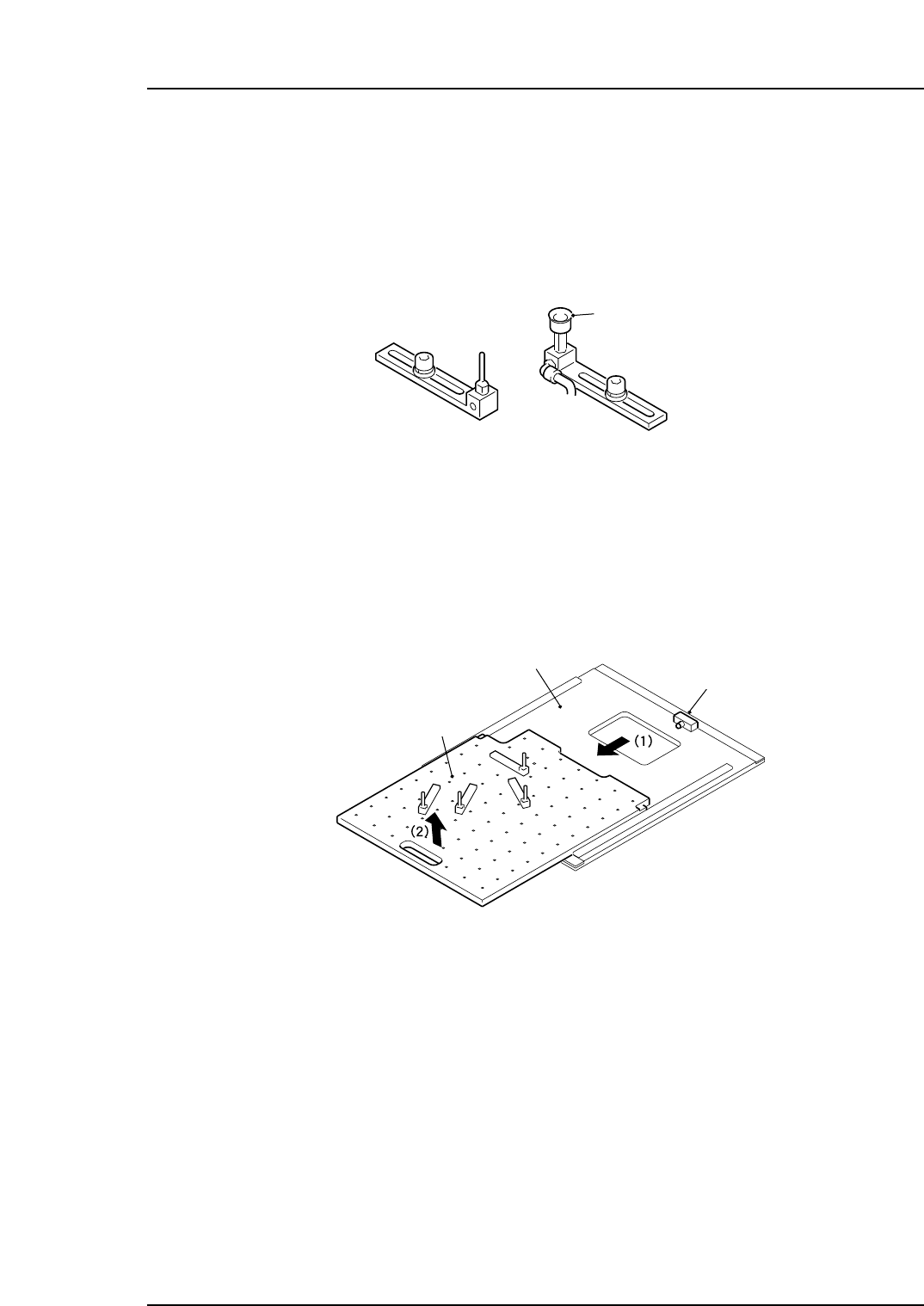
4. Pull the back-up plate sideways slightly, then lift it up to remove it.
Precautions when mounting/demounting the back-up plate:
• Use care to avoid interference between the plate and the sensor. Such interference
could break the sensor.
• Because the procedure is performed from the MFU side, use care to avoid
interference with the camera.
5. Detach the back-up pins by loosening their fastening bolt, and reposition them as
necessary.
6. When the back-up pins are in place, slide the back-up plate back onto the lifter. Be
sure to push it into the back-up plate until it contacts the block (refer to the
diagram above).
7. Before raising the lifter, make sure that the back-up pins do not interfere with the
adjustable side of the conveyor. If there is interference, reposition the back-up
pins.
XP1MC004E
Back-up plate
Panel lifter
Block
XP1MC003E
Vacuum pad
Back-up pin
Part 2 Chapter 2 Changing the Position of the Back-up Pins
Edition 3.0 2-2-1 XP-142E Mechanical Reference

Notes:
Part 2 Chapter 2 Changing the Position of the Back-up Pins
Edition 3.0 2-2-2 XP-142E Mechanical Reference
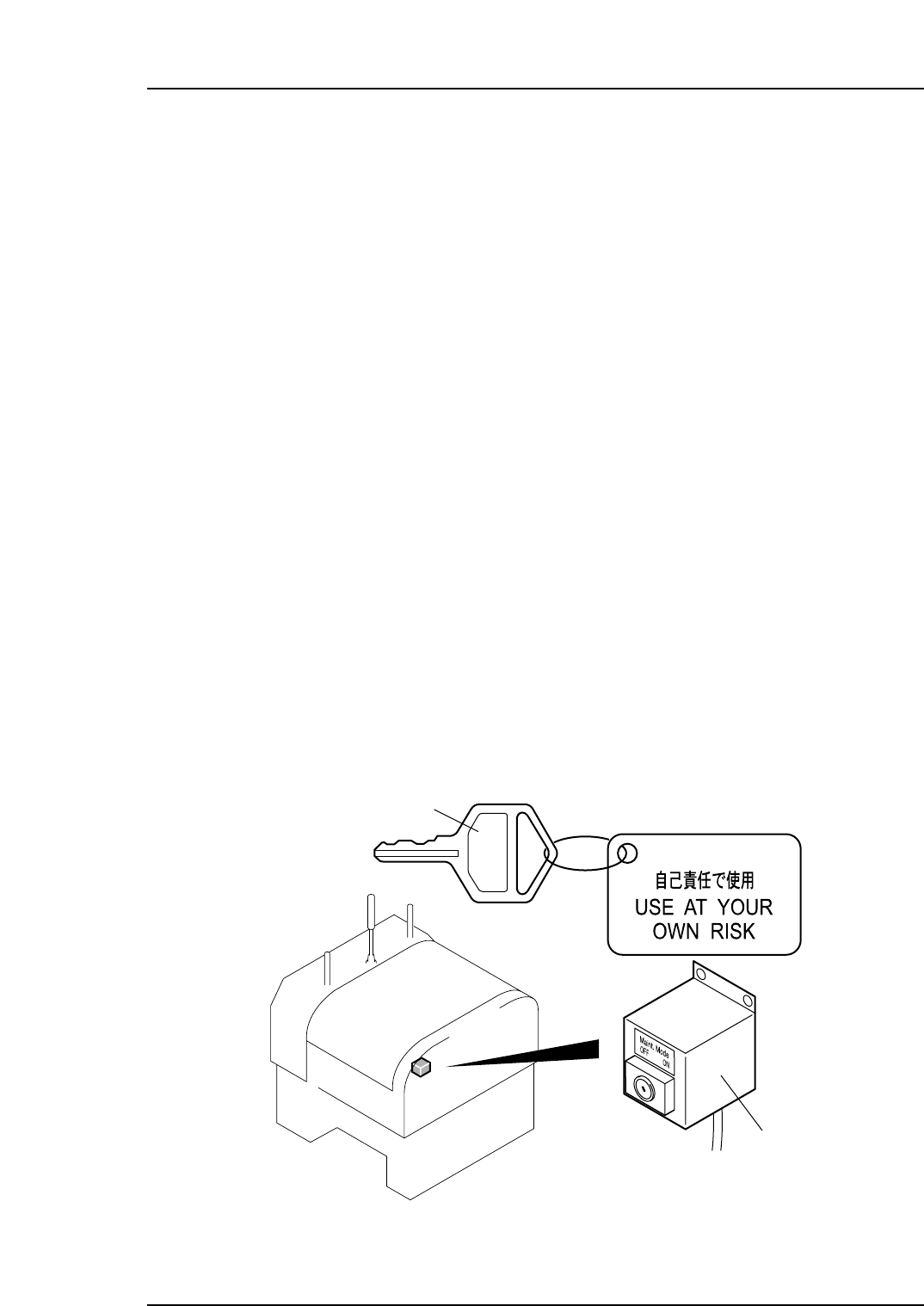
3. Using the Maintenance Key
Point
Maintenance and adjustment sometimes require operation of the servo motors with the
safety doors open. Special maintenance commands and a maintenance key are used in
such cases, allowing the servo system power to remain on while the safety doors are
open.
Features of the Special Maintenance Commands
• The servo system power supply is maintained for operation with the safety doors
open.
• The servo system power supply is maintained without having to clamp the MFUs.
• The maximum speed of the servo motors has been reduced during use of the
Special Maintenance commands.
• The servo motors stop immediately when the inching keys at the [JOG] screen are
released.
• The main operable parts are the servo motors, conveyor motors, the strobe lighting
and each I/O.
Procedure
1. From the [Main] screen of the control panel, select [Maintenance C] [Custom
Maintenance] to open the [JOG] screen.
2. When the message "Turn the Maintenance Switch ON." displays, press the
EMERGENCY STOP button and open the safety door.
3. Insert the maintenance key into the maintenance switch inside the machine, and
switch the key to ON.
XP1MC005E
Maintenance key
Maintenance switch
Part 2 Chapter 3 Using the Maintenance Key
Edition 3.0 2-3-1 XP-142E Mechanical Reference