LmrXP142机械手册.pdf - 第85页
1. Servo Amplifier Adjustments 1.1 Servo Amplifier Parameters 1. Check the servo amplifier parameters using the panel operator controls on the face of the amplifier. Digital operator JUSP-OP05A can also be used to check …

Part 4
Adjustments
1. Servo Amplifier Adjustments . . . . . . . . . . .4-1-1
This section explains adjustments
that can be performed by the user.
1. Servo Amplifier Adjustments
1.1 Servo Amplifier Parameters
1. Check the servo amplifier parameters using the panel operator controls on the face
of the amplifier. Digital operator JUSP-OP05A can also be used to check the Y, G,
F, R, Q, and Z servo amplifier parameters.
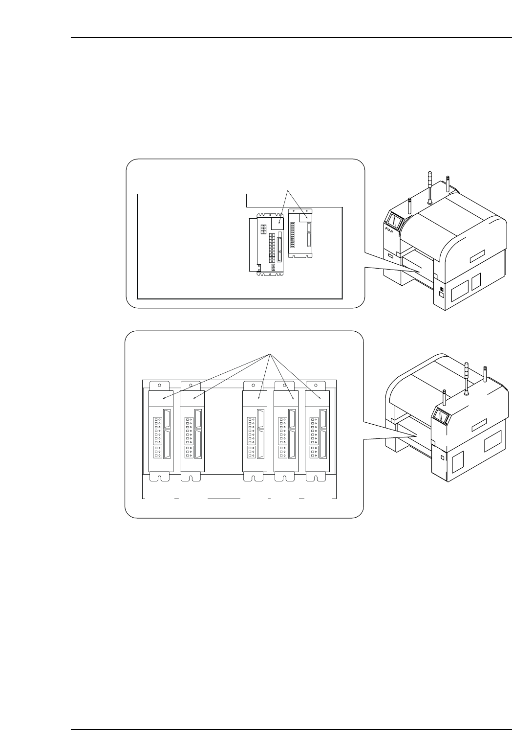
XP1MA007aE
Front (Side 1)
Rear (Side 2)
Servo box 1
LED display
X-axis
Y-axis
Servo box 2
LED display
G-axis F-axis R-axis Q-axis Z-axis
Part 4 Chapter 1 Servo Amplifier Adjustments
Edition 3.0 4-1-1 XP-142E Mechanical Reference
1.1.1 X-Axis Servo Amplifier (Q Series) Parameter Check
Procedure
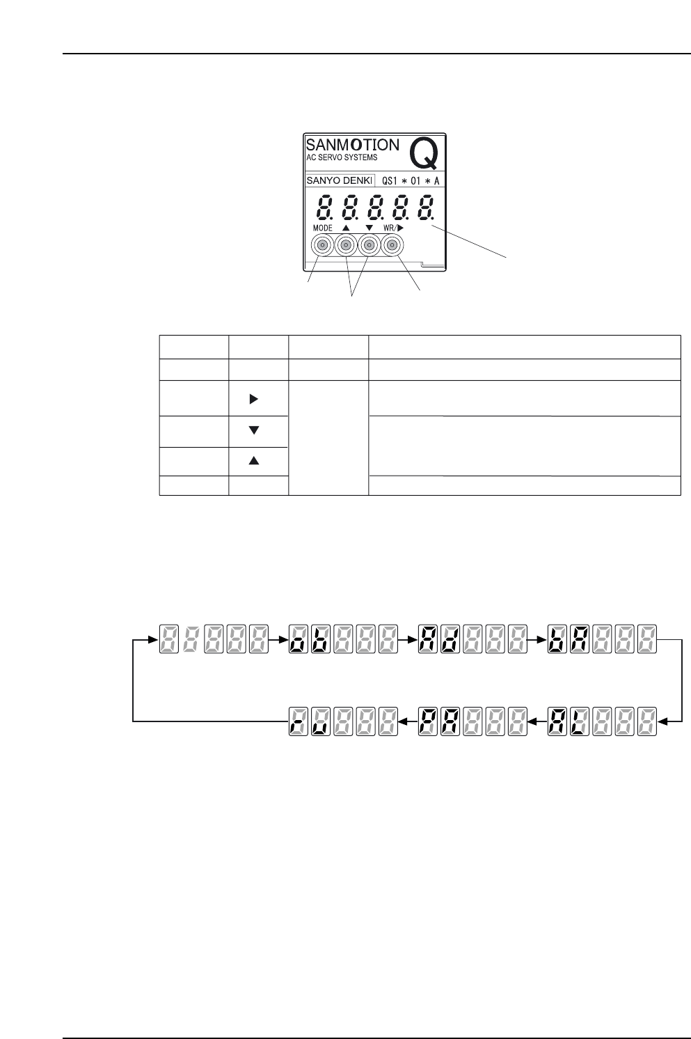
1. The display cycles through the following modes when the Mode Key is pushed.
XP1MA009E
Status display Monitor Test/Adjust Basic
System parameter edit Parameter edit Alarm trace
Mode Mode Mode Mode
Mode Mode Mode
XP1MA008E
Display: Five 7-segment digits
Key
WR Key WR
Mode
More than 1 s. Use to enter a selection and write-in edited data.
Cursor Key
Use to move the cursor. Push once to move to the next
selectable digit.
Mode Key
Push once to change the mode.
Up Key
Less than
1 second
Down Key
Push once to change the value of the digit where the
cursor is.
Hold in for more than 1 second to scroll among the select-
able values of the digit where the cursor is.
Display Time Held Function
Cursor/WR Key
Up/Down Key
Mode Key
Part 4 Chapter 1 Servo Amplifier Adjustments
Edition 3.0 4-1-2 XP-142E Mechanical Reference