00196715-04_IM_SSW_704_03_SP1_DE_EN - 第18页
Station Software 704.03 SP1 / Installation Manual Ausgabe 10/2011 Edition Figure 4-2: Hardware component s of the computer system fo r the SIPLACE X-series in two-compute r operation (block diagram) 18
Station Software 704.03 SP1 / Installation Manual Ausgabe 10/2011 Edition
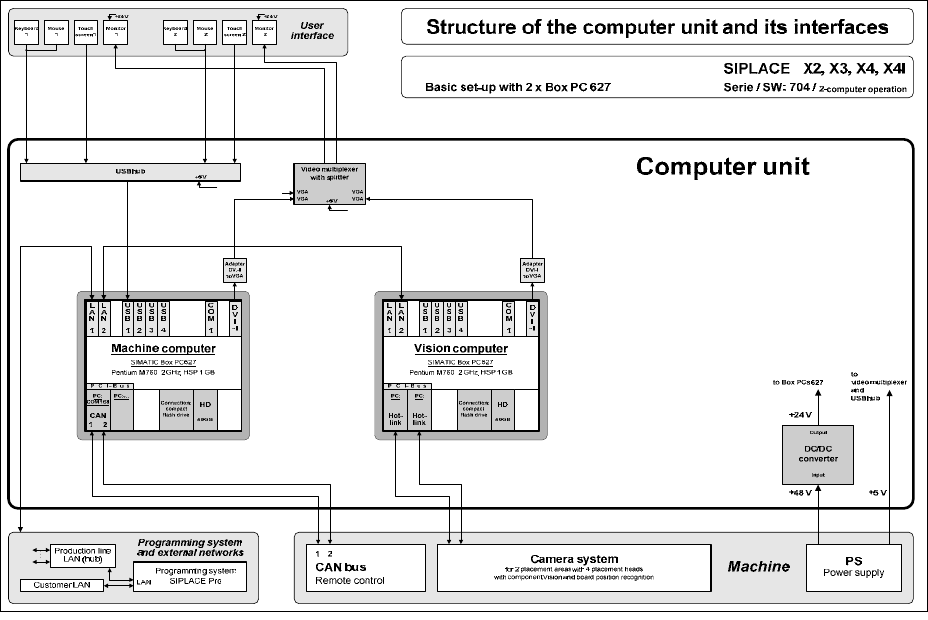
4.2 SIPLACE X- and SX-series hardware components
The following two diagrams show the hardware components of the computer system for the
SIPLACE X2, X3, X4 and X4I machines in two-computer operation:
Figure 4-1: Hardware components of the computer system for the SIPLACE X-series in two-computer operation (block
diagram)
17

Station Software 704.03 SP1 / Installation Manual Ausgabe 10/2011 Edition
Figure 4-2: Hardware components of the computer system for the SIPLACE X-series in two-computer operation (block
diagram)
18
Station Software 704.03 SP1 / Installation Manual Ausgabe 10/2011 Edition
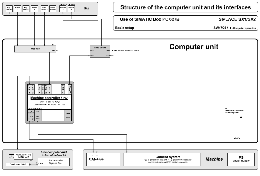
The following diagram shows the hardware components of the computer system for the SIPLACE
SX1/SX2 machine in one-computer operation:
Figure 4-3: Hardware components of the computer system for SIPLACE SX1/SX2 in one-computer operation (block
diagram)
19