00196715-04_IM_SSW_704_03_SP1_DE_EN - 第23页
Station Software 704.03 SP1 / Installation Manual Ausgabe 10/2011 Edition 4.3 Network configuration Figure 4-5: Network connections between the machine and SIPLACE Pro In two-computer operation a separate private network…

Station Software 704.03 SP1 / Installation Manual Ausgabe 10/2011 Edition
4.2.2 Machine/Vision computer (in one-computer operation)
Name SIMATIC Box PC 627B
CPU / clock frequency Core 2 Duo T7400 / 2,16 GHz
RAM 1 GB
Harddisk Yes
External DVD drive Yes
Internal DVD drive No
Serial interfaces 1
USB interfaces and
external USB hub
Yes
Network 2x 100 MBit
Table 4-5: Machine/Vision computer hardware SIPLACE SX1/2
Name SIMATIC Box PC 827B
CPU / clock frequency Core 2 Duo T7400 / 2,16 GHz
RAM 2 GB
Harddisk Yes
External DVD drive No
Internal DVD drive No
Serial interfaces 1
USB interfaces Yes
External USB hub No
Network 2x 100 MBit
Table 4-6: Machine/Vision computer hardware SIPLACE X-series and SX4
22
Station Software 704.03 SP1 / Installation Manual Ausgabe 10/2011 Edition
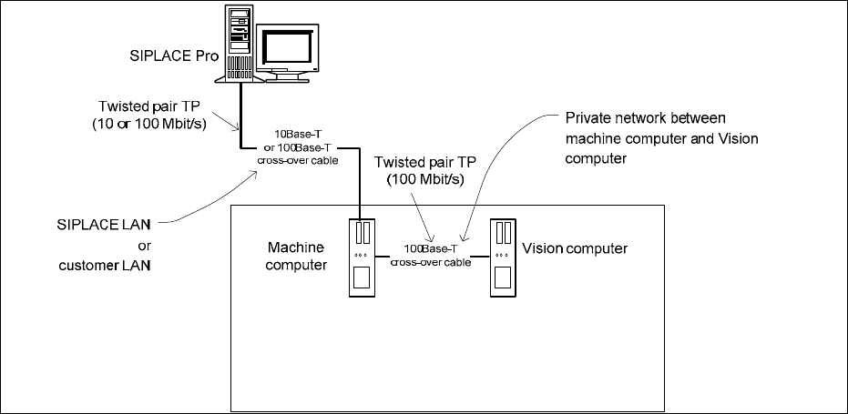
4.3 Network configuration
Figure 4-5: Network connections between the machine and SIPLACE Pro
In two-computer operation a separate private network (100 Mbit/s) is set up between the machine
computer and the Vision computer via a subnet mask.
Fixed IP addresses for the machine computer and the Vision computer can thus be assigned for all
SIPLACE machines. These IP addresses are not known outside the private network, for instance in
the SIPLACE LAN or customer LAN.
These IP addresses need not be further configured by the operator while the station software is
being installed.
23
Station Software 704.03 SP1 / Installation Manual Ausgabe 10/2011 Edition
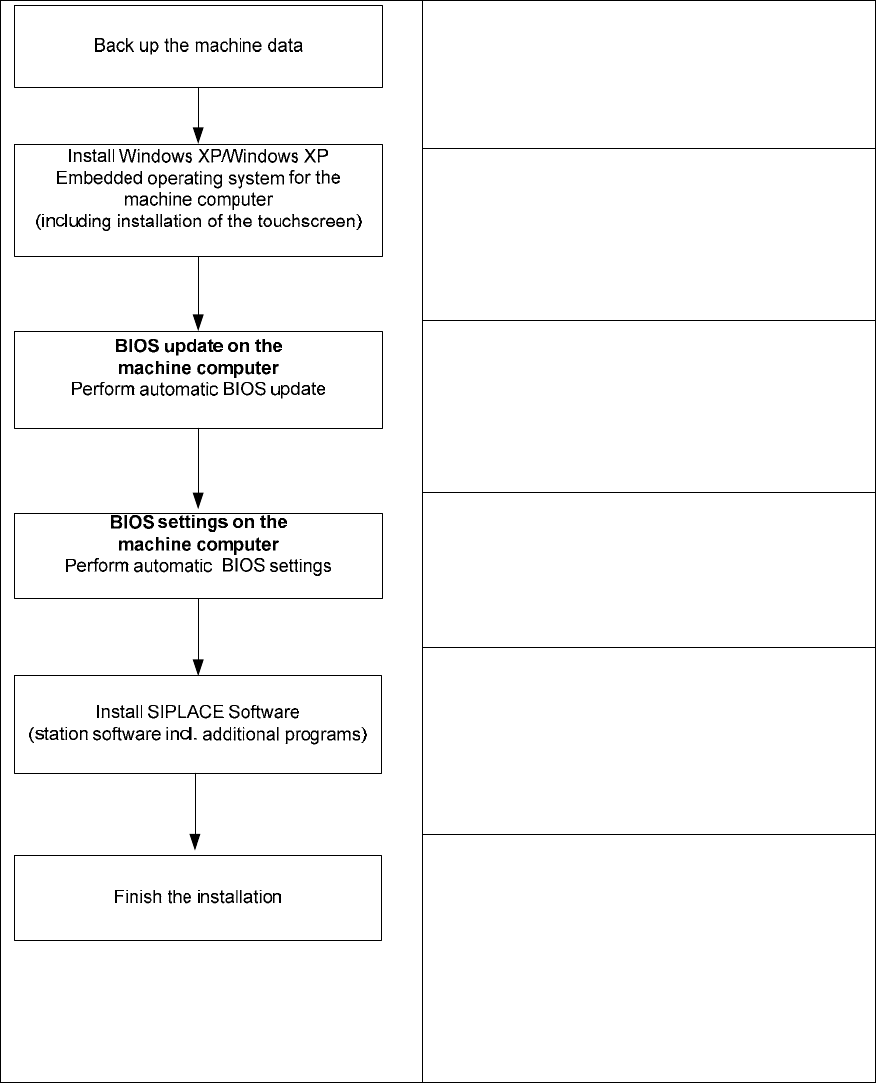
5 Installing the machine computer
5.1 Installation sequence
See separate Installation Manuals for details on
installing the Windows XP or Windows XP
Embedded operating system (item no.
00196151-xx and 00196737-xx respectively)
For details on calibrating the touchscreen, see
section 5.2.3.
See section 5.3.
See section 5.3.
See section 5.4.
See section 5.4.7.
Figure 5-1: Installation sequence
24