00191134-03.pdf - 第12页
GEM for SIPLACE V5.01 Page 12 of 252 ©Siemens AG, all rights reserved 1.4 *(0 &RPSOLDQFH6WDWHPHQW GEM COMPLIANCE ST ATEMENT FUNDAMENTAL GEM REQUIREMENT S IMPLEMENTED COMPLIANT State Models ✓ Yes ¨ No Equipment Pr o…

GEM for SIPLACE V5.01
©Siemens AG, all rights reserved page 11 of 252
operations with a Host Computer. The SIPLACE complies to the following GEM
document:
1. E30-1994
*(0 &RPSOLDQFH
This section clarifies which GEM functions are implemented in this Equipment. See
„GEM Compliance Statement“ on page 12.
The SIPLACE never sends S2F25 (Loopback Diagnostic) to the Host. It will send the
appropriate S2F26 in response to an S2F25 from the Host.
The SIPLACE never sends S9F13 (Conversation Timeout) to the Host. The Equipment
can be defined as having an „infinite timeout“ for conversations.
The SIPLACE never sends S10F7 (Multi-Block Not Allowed) to the Host. It will accept
incoming messages consisting of printable characters and a maximum size of 320
characters.
The SIPLACE will accept, but does not require the Inquire/Grant transaction
(S2F39/S2F40, S6F5/S6F6, S7F1/S7F2) for incoming primary multi-block messages.
GEM for SIPLACE V5.01
Page 12 of 252 ©Siemens AG, all rights reserved
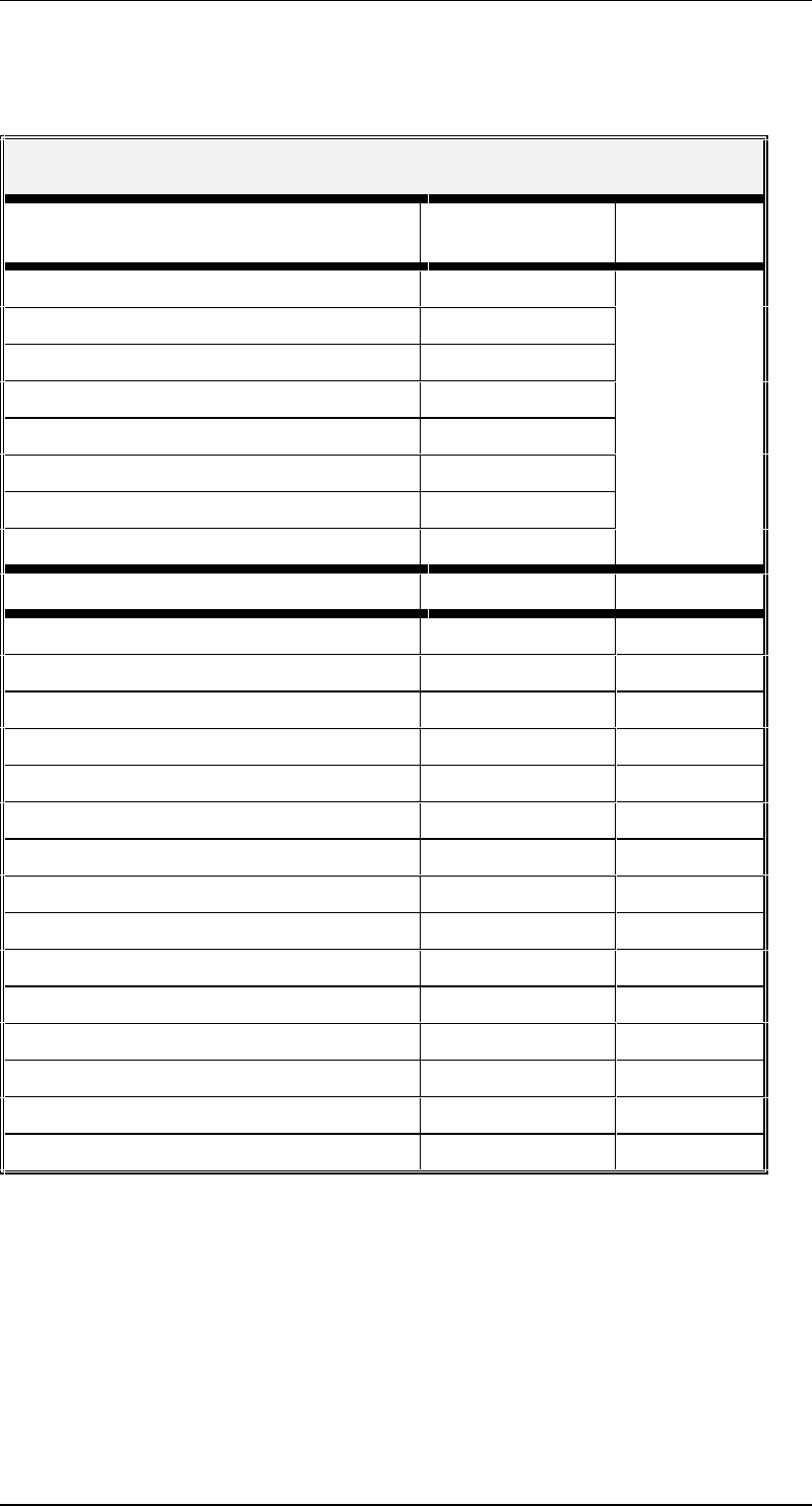
1.4 *(0 &RPSOLDQFH6WDWHPHQW
GEM COMPLIANCE STATEMENT
FUNDAMENTAL GEM REQUIREMENTS IMPLEMENTED
COMPLIANT
State Models ✓Yes ¨ No
Equipment Processing States ✓ Yes ¨ No ✓ Yes
S1,F13/F14 Scenario ✓ Yes ¨ No
Event Notification ✓ Yes ¨ No
On-line Identification ✓ Yes ¨ No
Error Messages ✓ Yes ¨ No ¨ No
Control (Operator Initiated) ✓ Yes ¨ No
Documentation ✓ Yes ¨ No
ADDITIONAL CAPABILITIES IMPLEMENTED COMPLIANT
Establish Communications ✓ Yes ¨ No ✓ Yes ¨ No
Dynamic Event Report Configuration ✓ Yes ¨ No ✓ Yes ¨ No
Variable Data Collection ✓ Yes ¨ No ✓ Yes ¨ No
Trace Data Collection ✓ Yes ¨ No ✓ Yes ¨ No
Status Data Collection ✓ Yes ¨ No ✓ Yes ¨ No
Alarm Management ✓ Yes ¨ No ✓ Yes ¨ No
Remote Control ✓ Yes ¨ No ✓ Yes ¨ No
Equipment Constants ✓ Yes ¨ No ✓ Yes ¨ No
Process Program Management * ✓ Yes ¨ No ✓ Yes ¨ No
Material Movement ✓ Yes ¨ No ✓ Yes ¨ No
Equipment Terminal Services ✓ Yes ¨ No ✓ Yes ¨ No
Clock ✓ Yes ¨ No ✓ Yes ¨ No
Limits Monitoring ✓ Yes ¨ No ✓ Yes ¨ No
Spooling ✓ Yes ¨ No ✓ Yes ¨ No
Control (Host Initiated) ✓ Yes ¨ No ✓ Yes ¨ No
* is only possible to have one program on the SIPLACE (the GEM standard requires
three)
7HUPLQRORJ\
The following terms are used throughout the document to refer to the various entities
interfacing with the SIPLACE:

GEM for SIPLACE V5.01
©Siemens AG, all rights reserved page 13 of 252
(TXLSPHQW The SIPLACE 80S-20 or SIPLACE 80F
4
with GEM/SECS II-Interface
2SHUDWRU The person who physically has access to the equipment’s material port(s)
and control panel. This is the person who is operating the SIPLACE.
+RVW The computer which is connected to the equipment via the SECSII-interface
6WDWH'LDJUDPV
This document uses several )LQLWH6WDWH0DFKLQH diagrams to describe the current
condition of the Equipment’s SECS link, material handling mechanisms, and process
cycle. Each Finite State Machine diagram includes a State Diagram and a complete
description of the states and state transitions.
All Finite State Diagrams have been prepared in the format specified in the GEM
standard. This notation is required as a fundamental part of GEM compliance and must
be included in the Equipment SECS Interface Documentation. This notation is the
„Statechart“ notation developed by David Harel.
The following are the major characteristics of this notation as it is used in this document:
Each state is represented by a rectangle with rounded corners.
A collection of sub-states may be grouped into a super-state.
The entity described by the diagrams will be in one and only one of the sub-states at all
times.
Variables representing the current state of an entity do not contain values for super-
states, only the lowest sub-state is represented.
State transitions are represented by single-headed arrows.
Each state transition is a Collection Event, and it has a unique Collection Event ID (CEID)
An arrow directly from a super-state to another state describes a Collection Event that can
occur while the entity is in any one of the sub-states contained in the super-state.
An arrow directly into a super-state to the + (history) symbol describes a transition to the
lowest sub-state which described the entity just before the transition out of the super-
state.
An arrow directly into a super-state to the & (conditional) symbol describes a transition to
a particular sub-state based on some other relevant data. The conditional data is not
represented in the diagram but is described in the associated text.