N7201A653E.pdf - 第119页
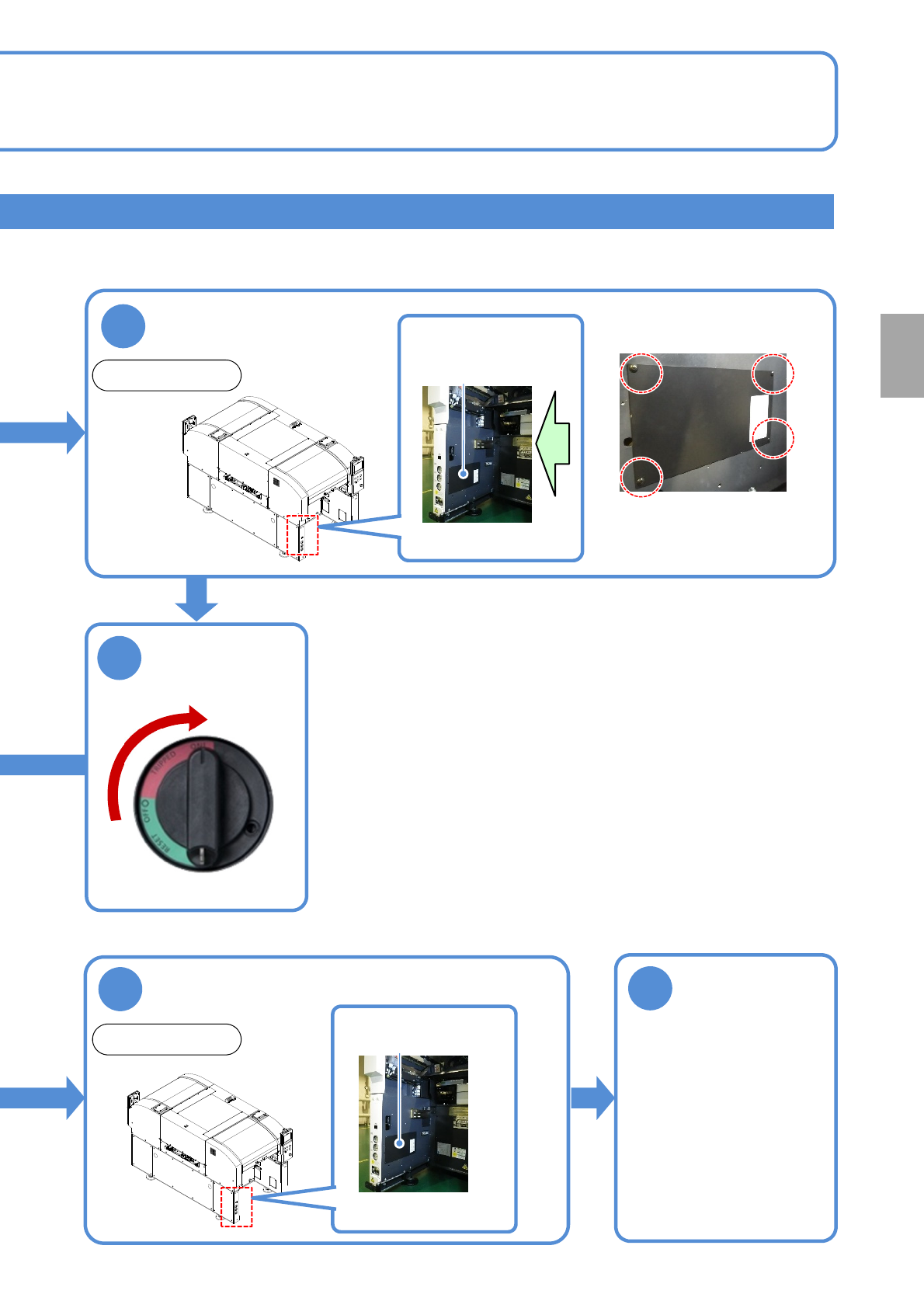
NPM- TT2 EJ M1EE-MB-04M-0 0 Front side Remove the cover inside of the cart ■ Image as seen from the arrow direction 2 4-1-1 -6 ● Screw: Four locations ● Remove screws Cover 3 Tu r n O N t h e main power switch 5 Attach t…
NPM-TT2 EJM1EE-MB-04M-00
4-1-1-5
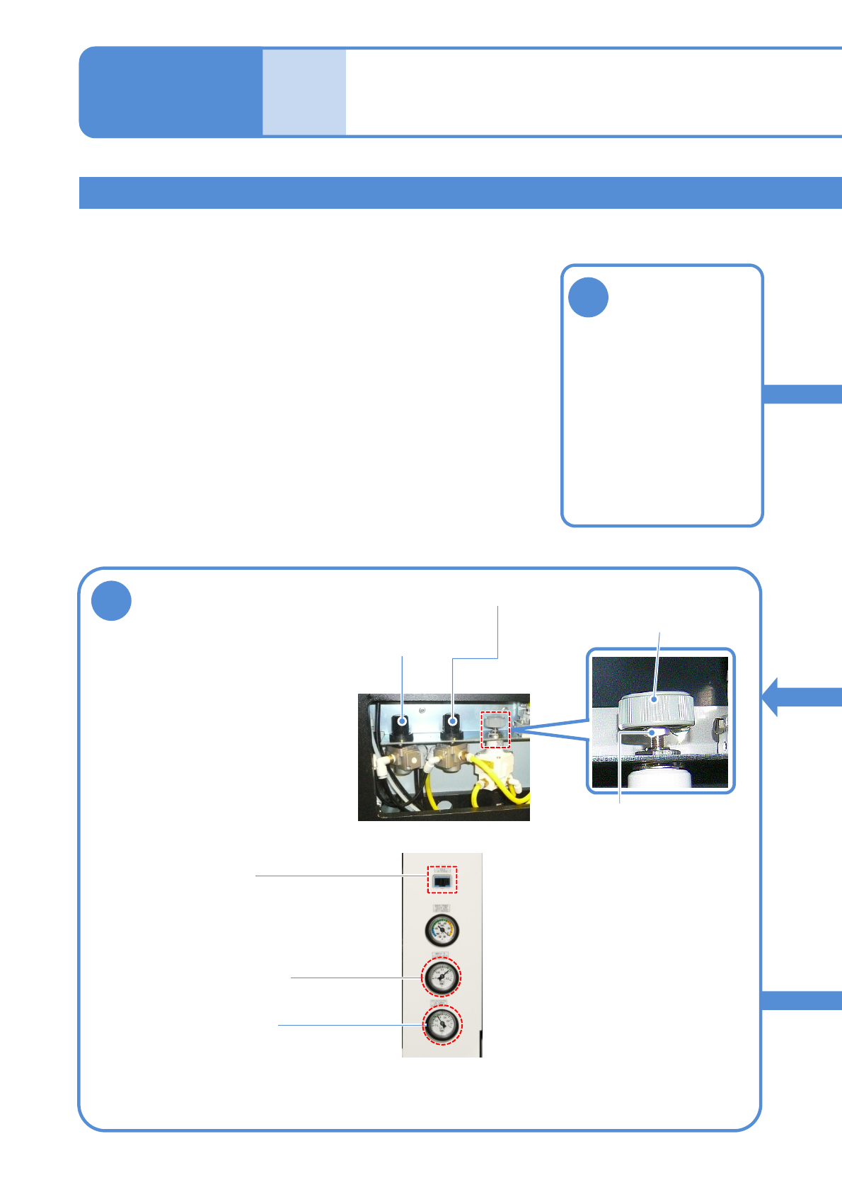
Adjusting the air pressure (pressure of cleaning blow , Option air pressure and vacuum break )
Tool used: Phillips screwdriver (No.2), spanner (10 mm) Time required: 20 minutes
●If cleaning blow pressure, Option air pressure and vacuum break pressure are out of prescribed value,
adjust them.
Before
opera-
tion
Maintenance
4-1-1
Inspecting the
pressure gauge 3
1
Adjust the pressure to be
within the range
4
Regulator knob
Cleaning blow regulator
knob
● How to use the regulator knob
1: Pull the knob up
2: Adjust it
3: Pull it down
(For cleaning blow pressure)
Vacuum break
pressure regulator
knob
Lock nut
●When the vacuum break regulator
is adjusted, loosen the lock nut.
After adjusted, tighten the nut.
Detach the tray
feeder or the
feeder cart
●For a tray feeder
(→ P.14-8)
●For a feeder cart
(→ P.3-2)
Cleanblowpressure
(0.13 to 0.14 MPa)
Optionairpressure
(0.4MPa)
Vacuum break
pressure
(8 to 12 kPa)
NPM-TT2 EJM1EE-MB-04M-00
Front side
Remove the cover
inside of the cart
■Image as seen from the
arrow direction
2
4-1-1-6
●Screw: Four locations
●Remove screws
Cover
3
Turn ON the
main power
switch
5
Attach the cover in
the main unit
6
Attach the tray
feeder or the
feeder cart
Front side
Cover
●For a tray feeder
(→ P.14-8)
●For a feeder cart
(→ P.3-2)
Every
24
hours
PeriodicPeriodic
inspection
ON
NPM-TT2 EJM1EE-MB-04M-00
Maintenance
4-2-1
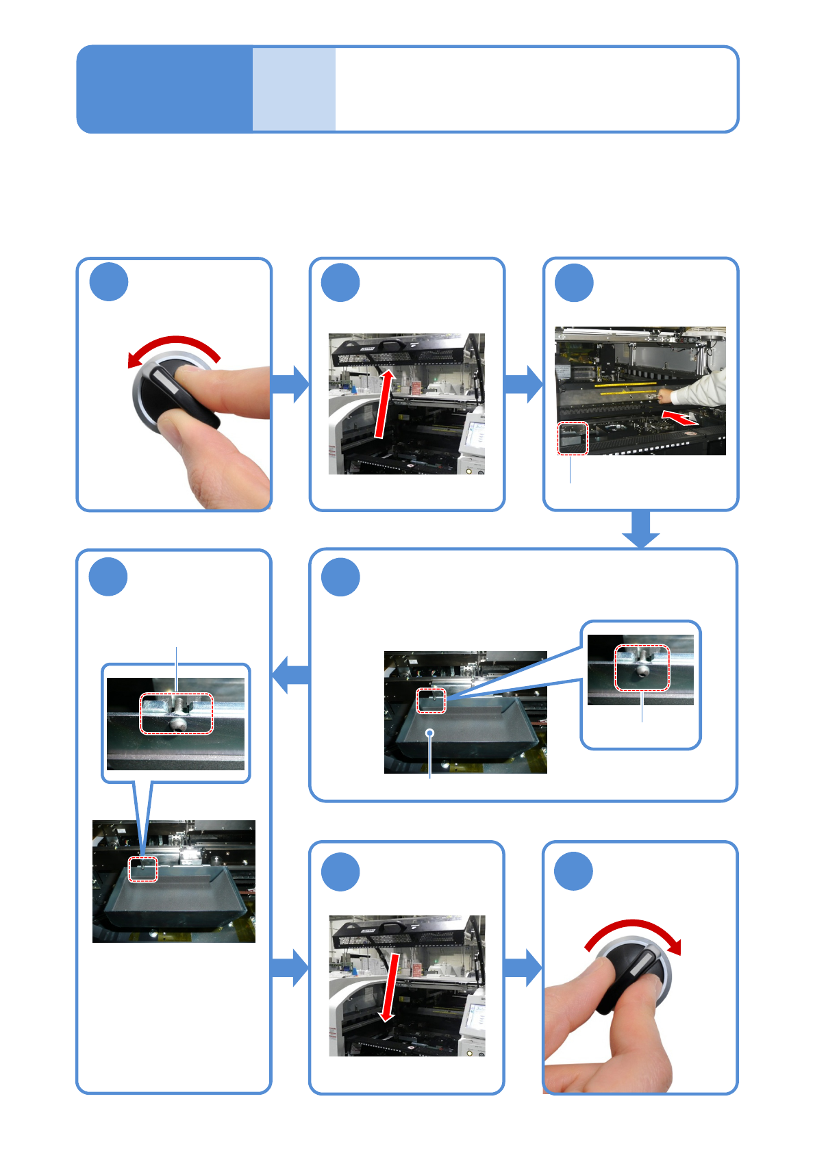
Cleaning the
components-ejection box
4
After
opera-
tion
Tool used: None Time required: 3 minutes (Total of the front and rear sides)
●Clean the components-ejection box.
●Clean it after operation.
●Not only after operation but also during production, clean it before it is full.
Remove components in the components-
ejection box
Put it back in its
original position
5
OFF
SERVO
1
2
3
SERVO
ON
6
7
Place the box by adjusting
the groove.
4-2-1
Components-ejection box
Lift it up from the bottom of the
components-ejection box to
remove.
Describes cleaning of the components-ejection box.
Components-ejection box
●Ensure that it is properly
placed.
(Otherwise, the error
message appears on the
screen and you cannot
activate the machine.)
Screw
Push the X-axis
inward