N7201A653E.pdf - 第251页
NPM- TT2 EJ M1EE-MB-11M-0 2 11 - 1 -12 Replacement Attaching the old type head (Removing fixing bolts) 1 2 3 4 When the old type head is attached to NPM-TT2, remove the unuse d fixing bolts before performing step 4 in “A…
NPM-TT2 EJM1EE-MB-11M-02
11-1-11
Maintenance
11-1
Head and nozzle
changer replacement 6
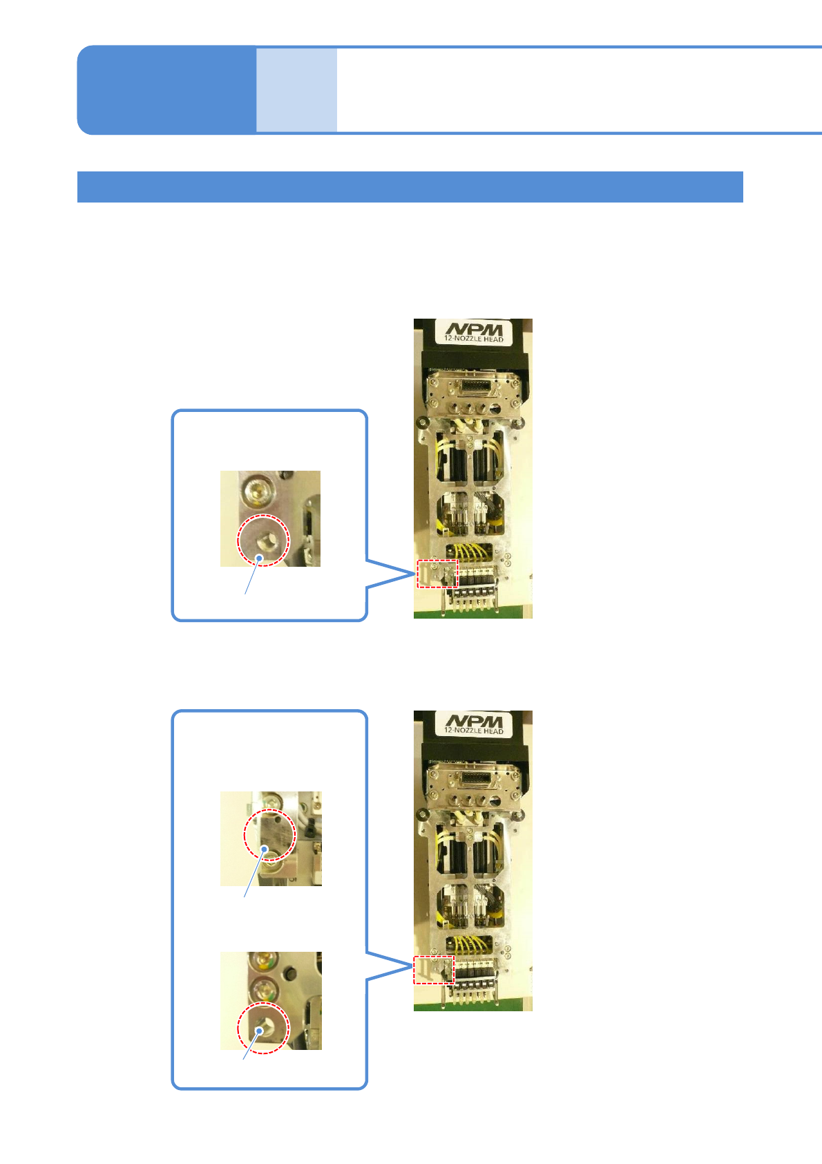
Old type head
The old type head is fixed with three bolts. (For the current head, use four bolts to fix.)
For details of the difference of the current head and old type head, see below.
When the old type head is attached on NPM-TT2, you need to remove the unused fixing bolts.
For details, see the subsequent pages.
■For current head
■For old type head
Screw hole which locates the
lower left part viewed from the
head attachment face
No hole or circular hole
which locates the lower
left part viewed from the
head attachment face
Circular hole
No hole
Screw hole
NPM-TT2 EJM1EE-MB-11M-02
11-1-12
Replacement
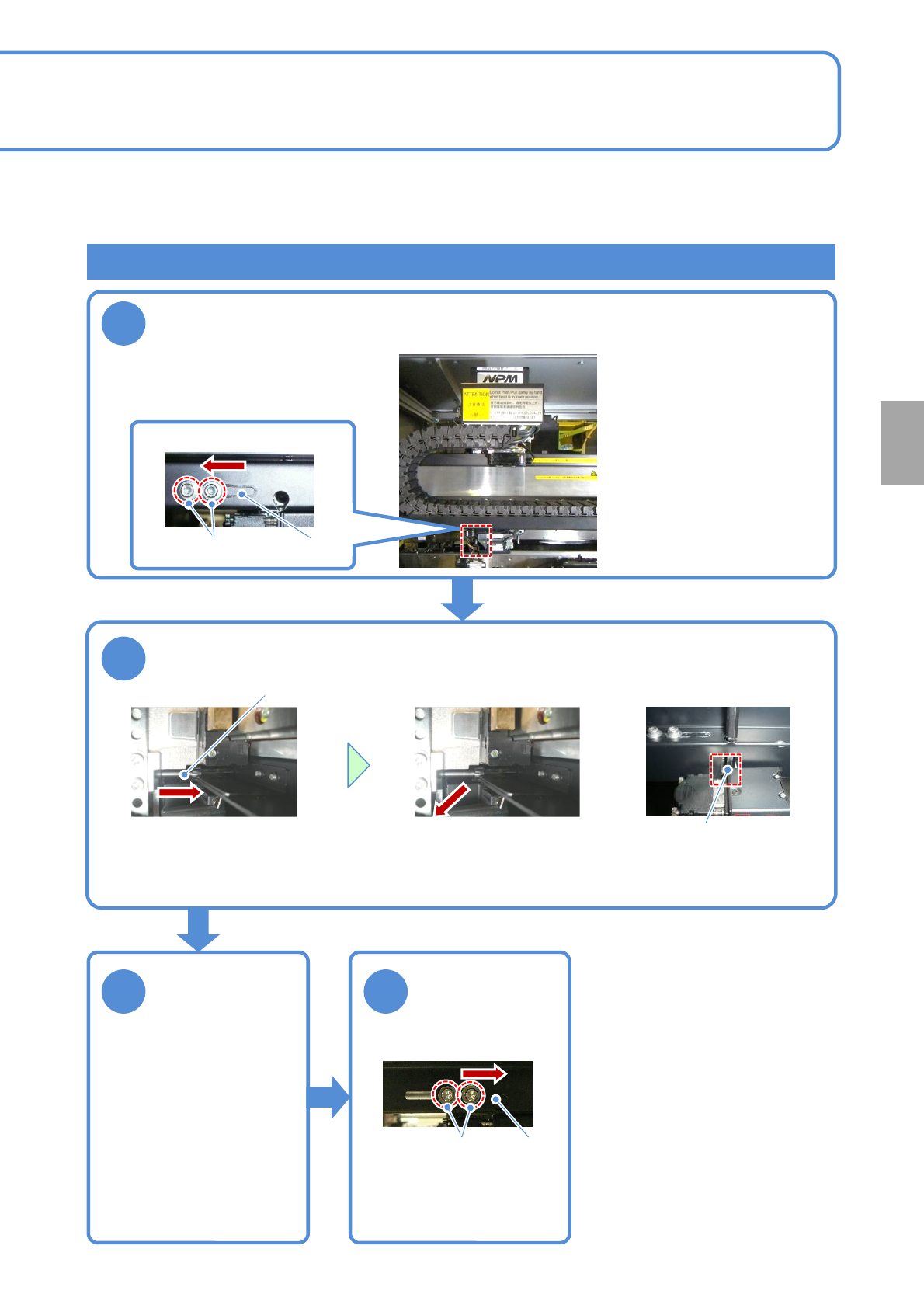
Attaching the old type head (Removing fixing bolts)
1
2
3 4
When the old type head is attached to NPM-TT2, remove the unused fixing bolts before performing step 4 in
“Attaching a head” (→P.11-1
-7) and fix the removed bolts to the storage place in the machine. The operations
are described here.
Tool used: Allen wrench (5mm and 2.5mm) Time required: 3 minutes
Open the shutter and move the head to the position where you can
see the bolt. (Align the center of the head to the one of the line
camera)
Lower left of a head
Shutter
Remove a fixing bolt
Fixing bolt
●Using the Allen wrench,
turn the bolt and pull it
toward you.
●Remove the fixing bolt
from the plate groove.
Plate groove
Close the shutter
Shutter
X-axis bottom surface
Tighten the bolt
Loosen the bolt
Store the
removed fixing
bolt
●You need to carry out the
operation that the fixing bolts are
removed from the storage
position and put them back to the
original position. After the old type
head is removed, put the fixing
bolts back to the original position
in the reverse order by referring
to the operation to remove the
fixing bolts described in this page.
■When the old type head is
removed and the current head
is attached
NPM-TT2 EJM1EE-MB-11M-02
11-2-1-1
1
1
3
+
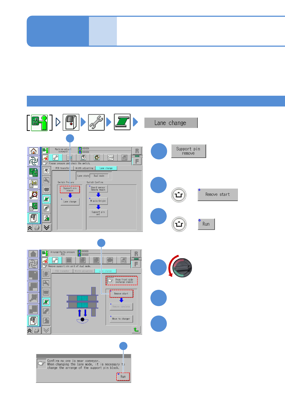
(The message of removing the support
pin unit is displayed)
Confirm the message
2
+
2
Confirm the message
Mode
switch
Maintenance
11-2-1
Switching to the single
lane mode 1
4
Turn OFF the main
power switch
6
5
Detach the tray feeder
(→P.14-8)
Open the safety cover
Switching the mode allows you to use the machine either for single conveyor or dual conveyor. Switching
varies depending on component supply specification. Please switch the mode based on the procedure used
for each specification. In this section, we explain how to switch from dual conveyor to single conveyor.
●When lane mode is changed, the layout of the support blocks must be changed as well.
●Make sure to use the support block suitable for each lane mode; otherwise the machine does not operate
properly.
For front/rear tray feeder specification 1
(The PCB-support blocks in lanes 1
and 2 go up so that they are ready to
be removed)
OFF
3