N7201A653E.pdf - 第266页
NPM- TT2 EJ M1EE-MB-11M-0 2 1 1-2-2 -3 1 3 + 4 2 + 1 2 3 4 5 + 6 + Confirm the message 5 7 Detach the feeder cart (→P.3-2) 9 8 Open the safety cover 10 Open the feeder table cover 6 Confirm the message Mode switch Mainte…
NPM-TT2 EJM1EE-MB-11M-02
11-2-2-2
Close the safety cover
Turn ON the main
power switch
+
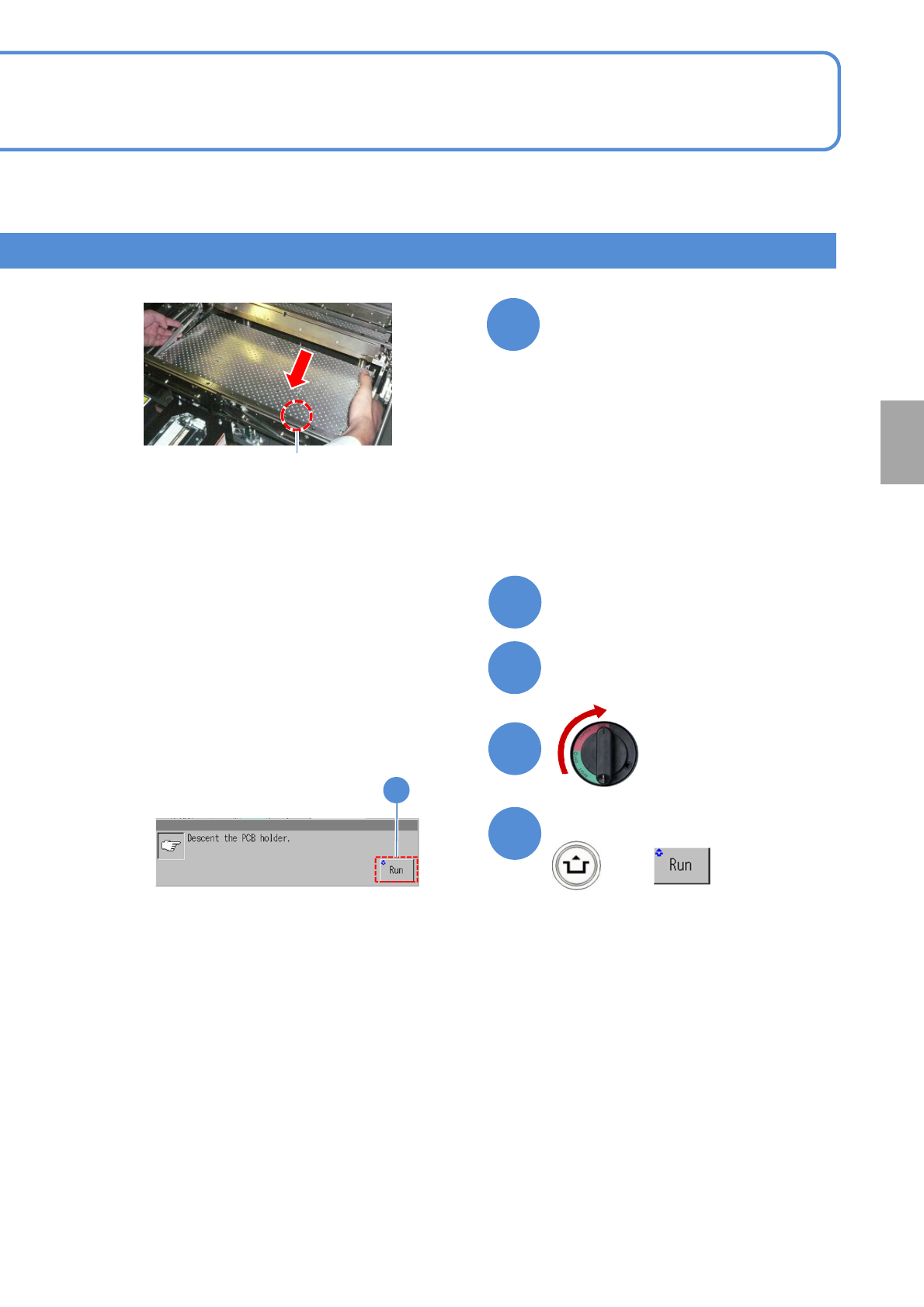
(The PCB support block lowers)
Confirm the message
14
Attach the tray feeder
(→P.14-8)
Replacement
ON
13
14
12
11
10
Guide pin
Install the PCB support block
(Both lane 1 and 2)
●Adjust the guide pins on the main unit
to the holes on the PCB support
block.
●Replace the PCB support block or
change the layout. For the product
number and the layout of the PCB
support block, see “5-3 Cleaning the
PCB-support blocks.”
NPM-TT2 EJM1EE-MB-11M-02
11-2-2-3
1
3
+
4
2
+
1
2
3
4
5
+
6
+
Confirm the message
5
7
Detach the feeder cart
(→P.3-2)
9
8
Open the safety cover
10
Open the feeder table cover
6
Confirm the message
Mode
switch
Maintenance
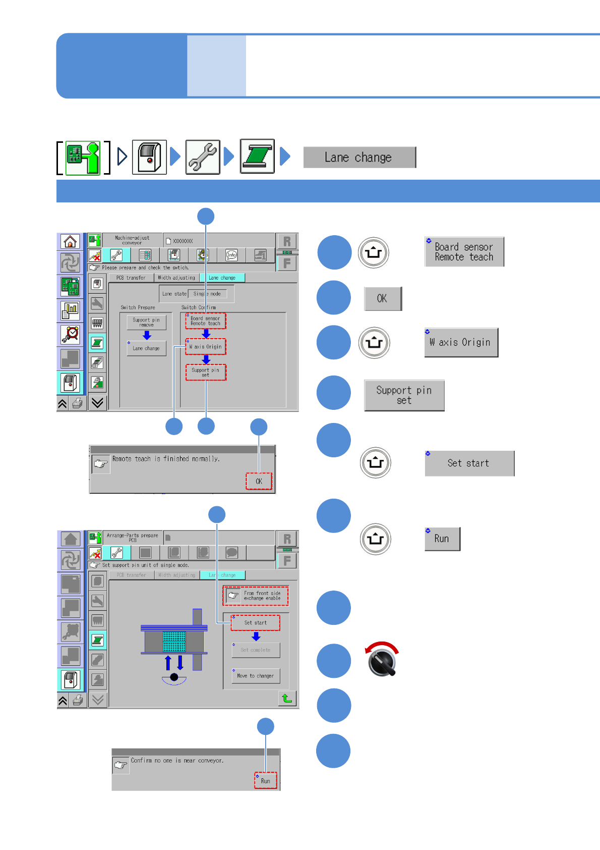
11-2-2
Confirming switch 2
(The PCB-support blocks in lanes 1
and 2 go up so that they are ready
to be removed)
For specification for feeder cart(s) on either the front or rear,
Servo switch OFF
NPM-TT2 EJM1EE-MB-11M-02
11-2-2-4
+
Attach the feeder cart
(→P.3-2)
Close the safety cover
Close the feeder table cover
16
or on both the front and rear
Replacement
Servo switch ON
16
15
13
14
12
11
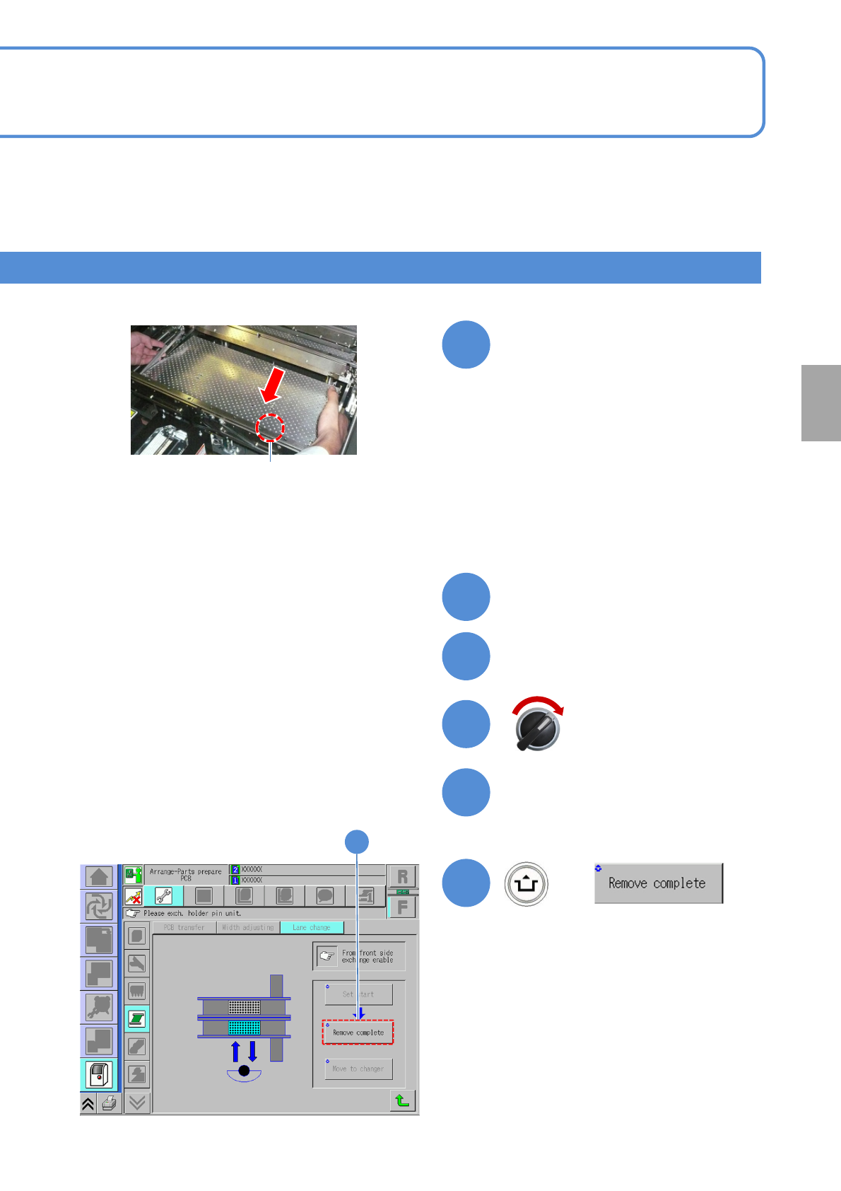
Guide pin
Install the PCB support block
(Both lane 1 and 2)
●Adjust the guide pins on the main unit
to the holes on the PCB support
block.
●Replace the PCB support block or
change the layout. For the product
number and the layout of the PCB
support block, see “5-3 Cleaning the
PCB-support blocks.”