N7201A653E.pdf - 第313页
NPM- TT2 EJ M1EE-MB-13M-0 2 5 Set the plane calibration jig ① Manually m ove the calibration jig and align the left end o f the plane calibration jig to the left side guide line on the PCB conveyor upper surface. (Both o…
NPM-TT2 EJM1EE-MB-13M-02
+
1
Plane
calibratio
n XY
Plane calibration XY
(PC size conveyor) 1
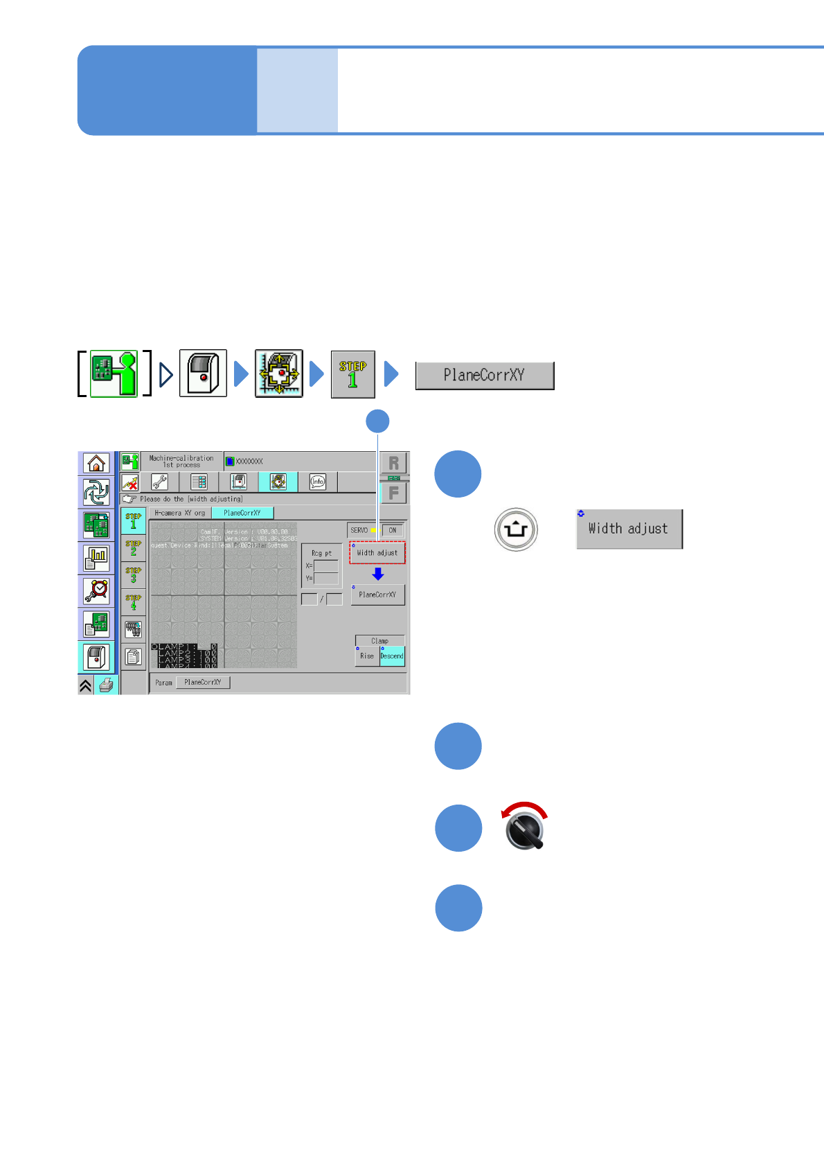
Explains the method for calibrating the plane calibration XY.
This operation procedure is also shared by the 8- and 3-nozzle heads.
●Place the plane calibration jig on the transfer conveyor to the left or right of the machine by hand and
operate it. (Two plane calibration jigs: N210141055AB)
●Perform calibration on lane 1 and 2 at once.
●Do not turn OFF the power of the machine during calibration.
●Remove all the PCB support pins before performing plane calibration.
●If you cannot set a plane calibration jig, manually load the PCB from the pre-process machine and set the
jig using the workbench (please prepare yourself).
Check that there are no PCBs
present inside the machine
●If ‘error’ message appears, remove all
the PCBs remaining inside the machine,
and try again.
1
(The width is adjusted)
(The head moves to the retraction
position.)
Maintenance
13-3-1
2
Prepare for the first plane
calibration XY
4
3
Open the safety cover
Servo switch OFF
13-3-1-1
NPM-TT2 EJM1EE-MB-13M-02
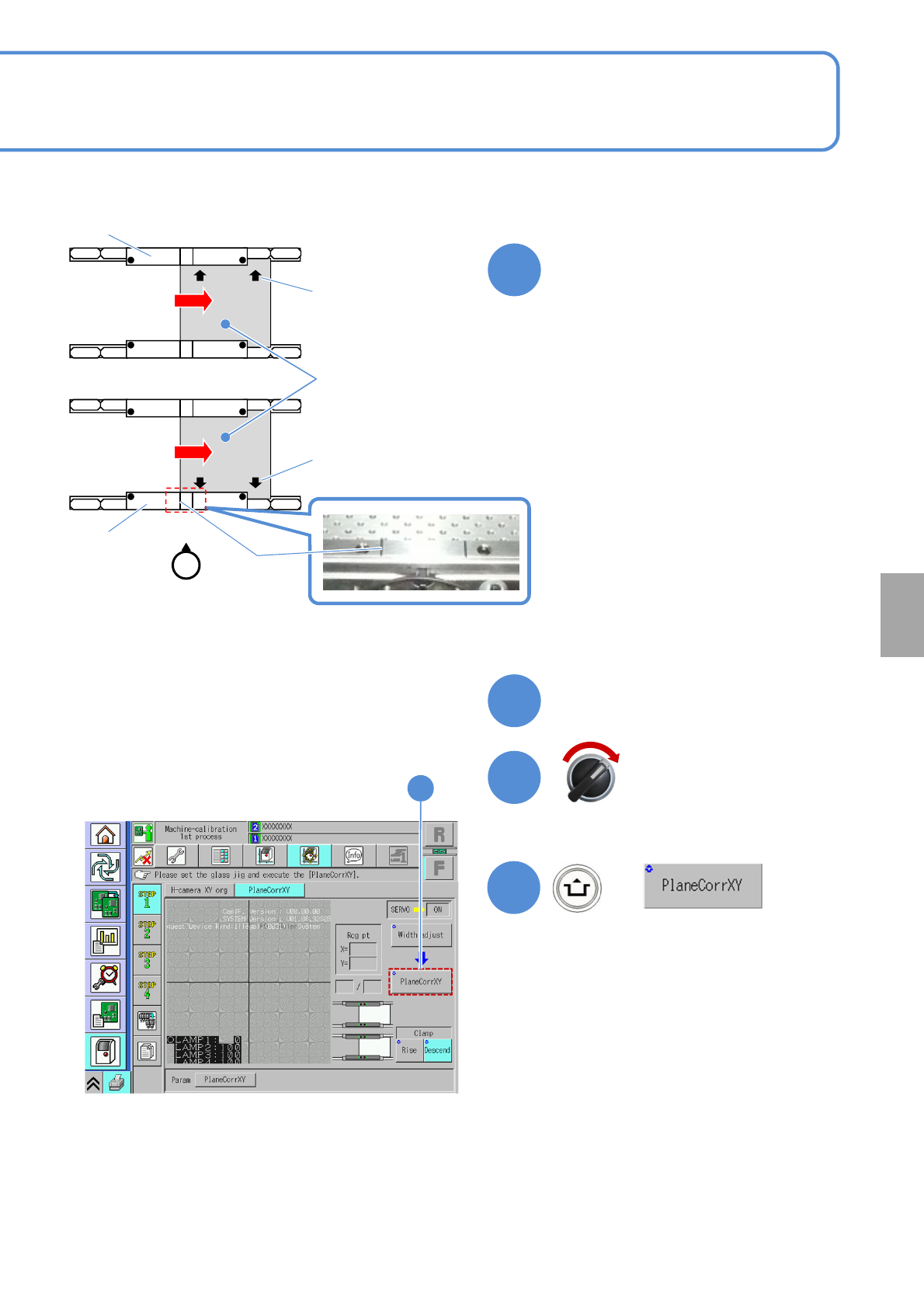
5
Set the plane calibration jig
①Manually move the calibration jig and
align the left end of the plane
calibration jig to the left side guide line
on the PCB conveyor upper surface.
(Both on lane 1 and 2. Common in
each PCB flow direction)
②Set the reference mark on the plane
calibration jig to the reference rail.
③Attach the plane calibration jig to the
reference rail.
Calibration
6
Close the safety cover
7
Servo switch ON
+
8
8
●If you cannot set a plane calibration jig,
manually load the PCB from the pre-
process machine and set the jig using
the workbench (please prepare
yourself).
Operator
Guide line
Reference mark
Reference mark
Reference rail
Reference rail
Lane 1
Lane 2
Plane
calibration jig
13-3-1-2
●You can also remove the feeder cart
and set a plane calibration jig.
NPM-TT2 EJM1EE-MB-13M-02
Plane
calibratio
n XY
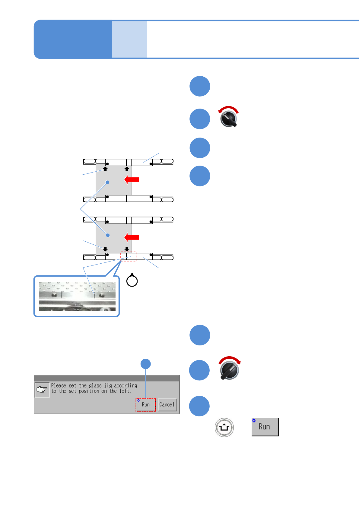
9
Prepare for the second plane
calibration XY
11
10
Open the safety cover
12
Set the plane calibration jig
Maintenance
13-3-1
①Manually move the calibration jig and
align the right end of the plane
calibration jig to the right side guide
line on the PCB conveyor upper
surface. (Both on lane 1 and 2.
Common in each PCB flow direction)
②Set the reference mark on the plane
calibration jig to the reference rail.
③Attach the plane calibration jig to the
reference rail.
13
Close the safety cover
14
15
Confirm the message
+
15
Servo switch OFF
Servo switch ON
Operator
Guide line
Reference mark
Reference mark
Reference rail
Reference rail
Lane 1
Lane 2
Plane
calibration jig
●If you cannot set a plane calibration jig,
manually load the PCB from the pre-
process machine and set the jig using
the workbench (please prepare
yourself).
13-3-1-3
Plane calibration XY
(PC size conveyor) 2
●You can also remove the feeder cart
and set a plane calibration jig.
(Plane calibration XY is measured on the
front head and rear head, in that order)
(After measurement, the head moves to the
retraction position)