N7201A653E.pdf - 第319页
NPM- TT2 EJ M1EE-MB-13M-0 2 5 Set the plane calibration jig ① Manually m ove the calibration jig and align the left end o f the plane calibration jig to the left side guide line on the PCB conveyor upper surface. (Common…
NPM-TT2 EJM1EE-MB-13M-02
+
1
Plane
calibratio
n XY
Plane calibration XY
(M size conveyor) 1
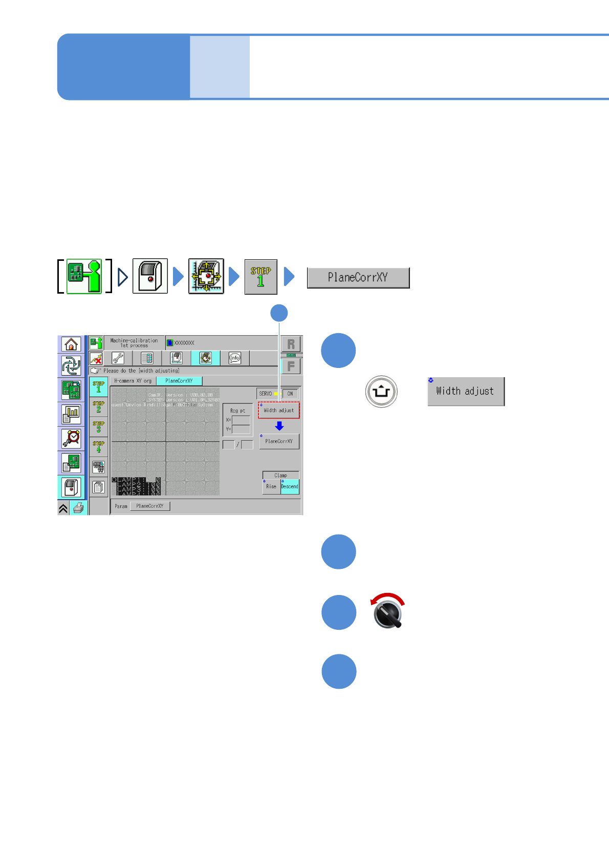
Explains the method for calibrating the plane calibration XY.
This operation procedure is also shared by the 8- and 3-nozzle heads.
●Place the plane calibration jig on the transfer conveyor to the left or right of the machine by hand and
operate it. (One plane calibration jigs: N210147296AC)
●Do not turn OFF the power of the machine during calibration.
●Remove all the PCB support pins before performing plane calibration.
●If you cannot set a plane calibration jig, manually load the PCB from the pre-process machine and set the
jig using the workbench (please prepare yourself).
Check that there are no PCBs
present inside the machine
●If ‘error’ message appears, remove all
the PCBs remaining inside the machine,
and try again.
1
(The width is adjusted)
(The head moves to the retraction
position.)
Maintenance
13-3-2
2
Prepare for the first plane
calibration XY
4
3
Open the safety cover
Servo switch OFF
13-3-2-1
NPM-TT2 EJM1EE-MB-13M-02
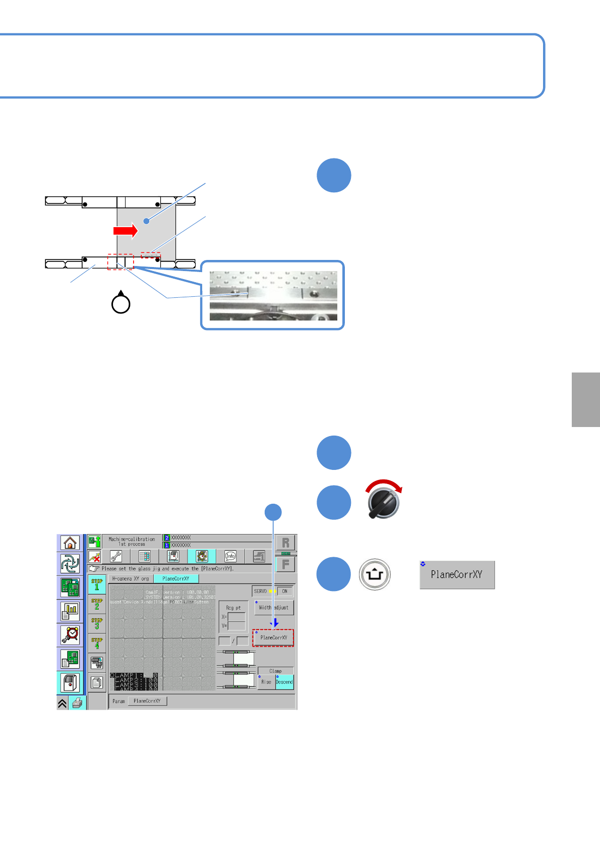
5
Set the plane calibration jig
①Manually move the calibration jig and
align the left end of the plane
calibration jig to the left side guide line
on the PCB conveyor upper surface.
(Common in each PCB flow direction)
②Set the reference mark on the plane
calibration jig to the reference rail.
③Attach the plane calibration jig to the
reference rail.
Calibration
6
Close the safety cover
7
Servo switch ON
+
8
8
●If you cannot set a plane calibration jig,
manually load the PCB from the pre-
process machine and set the jig using
the workbench (please prepare
yourself).
13-3-2-2
Plane
calibration jig
Reference mark
‘FIXED RAIL SIDE(TYPEA)’
Guide line
Operator
Reference rail
●You can also remove the feeder cart
and set a plane calibration jig.
NPM-TT2 EJM1EE-MB-13M-02
Plane
calibratio
n XY
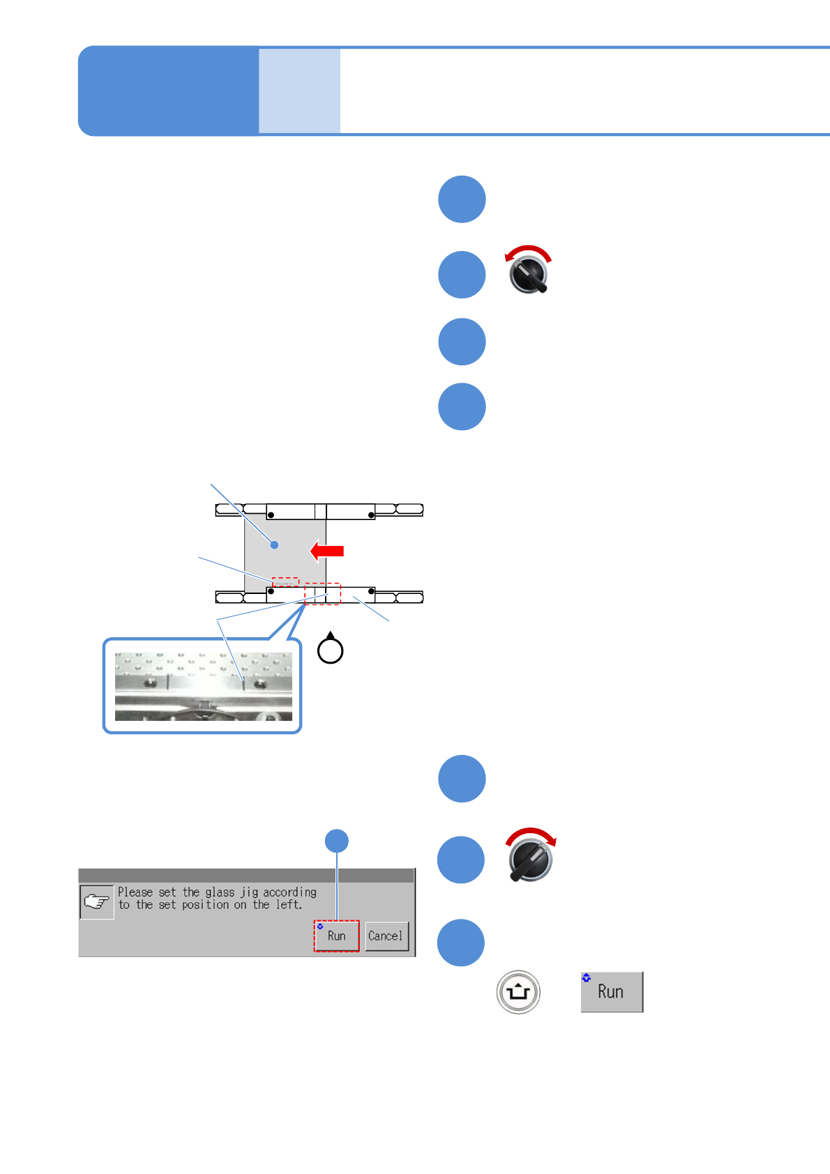
9
Prepare for the second plane
calibration XY
11
10
Open the safety cover
12
Set the plane calibration jig
Maintenance
13-3-2
①Manually move the calibration jig and
align the right end of the plane
calibration jig to the right side guide
line on the PCB conveyor upper
surface. (Common in each PCB flow
direction)
②Set the reference mark on the plane
calibration jig to the reference rail.
③Attach the plane calibration jig to the
reference rail.
13
Close the safety cover
14
15
Confirm the message
+
15
Servo switch OFF
Servo switch ON
Operator
●If you cannot set a plane calibration jig,
manually load the PCB from the pre-
process machine and set the jig using
the workbench (please prepare
yourself).
13-3-2-3
Plane
calibration jig
Reference mark
‘FIXED RAIL SIDE(TYPEA)’
Guide line
Reference rail
Plane calibration XY
(M size conveyor) 2
●You can also remove the feeder cart
and set a plane calibration jig.
(Plane calibration XY is measured on the
front head and rear head, in that order)
(After measurement, the head moves to the
retraction position)