N7201A653E.pdf - 第338页
NPM- TT2 EJ M1EE-MB-13M-0 2 Height sensor (option) 1 Select a table ● Select a table to perform calibration. (Work only at the front side) 1 The surface heig ht of several points on the PCB top surface is measured by the…

NPM-TT2 EJM1EE-MB-13M-02
13-6-6
Calibration
NPM-TT2 EJM1EE-MB-13M-02
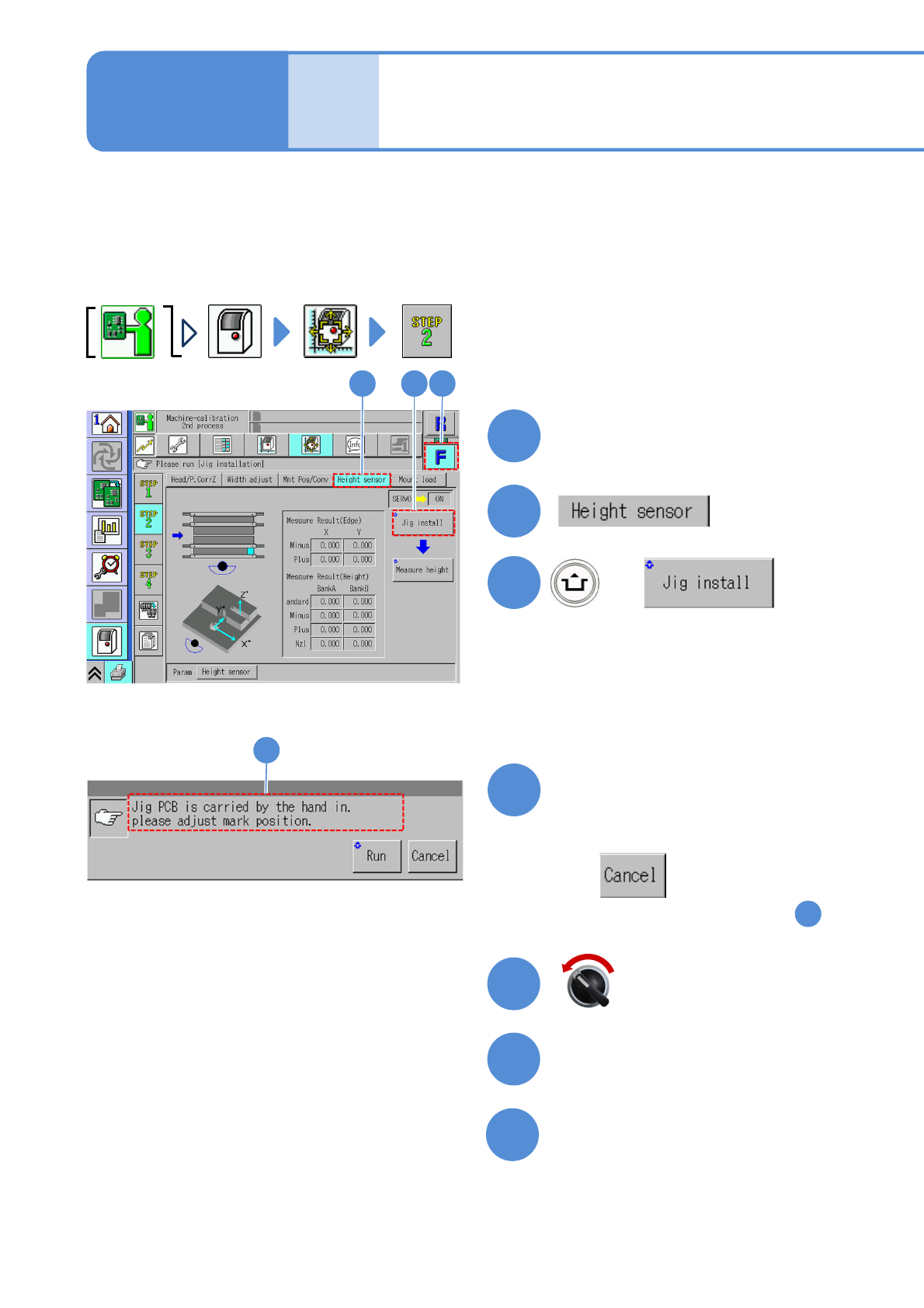
Height sensor (option) 1
Select a table
●Select a table to perform calibration.
(Work only at the front side)
1
The surface height of several points on the PCB top surface is measured by the height sensor, and
according to the result, PCB warpage condition is predicted and the nozzle lowering position is controlled
for placement operation. This operation procedure is also shared by the 8- and 3-nozzle heads.
●Remove all support pins before performing calibration.
●If the height sensor jig cannot be set up, manually load a PCB from the pre-process machine and set it
up using a workbench (please prepare yourself.)
2
+
3
Maintenance
13-7
12 3
●If there is PCB, remove it followed by
the instruction on the screen.
4
Confirm the message
■When you do not work
(The head remains as it is in )
1
4
(The width is adjusted)
(The head moves to the retraction
position)
Open the safety cover
6
5
7
Remove the PCB-support pin as
necessary
13-7-1
Servo switch OFF
(Confirm whether any PCB remains on
the transfer rail)
NPM-TT2 EJM1EE-MB-13M-02
11
13-7-2
8
Operator
Close the safety cover
9
10
+
(The head moves to the set position)
11
Open the safety cover
13
12
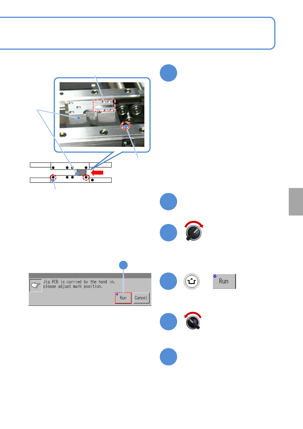
Measurement
part
●Confirm that there is no contamination
or stain on the measurement part.
●For calibration of the height sensor,
jigs on both the front and rear heads
are set to lane 1.
●Push the jig to the fixed side on the
rail, and set the jig as the right edge of
the jig matches to the mark on the
conveyor. (The picture on the right
shows for flowing from left to right)
●For flowing from right to left, the left
edge of the jig shall be matched to the
mark on the conveyor.
Slide and set the height sensor
jig from the downstream side
Height
sensor
jig
Calibration
Servo switch ON
Servo switch OFF
Fixed mark
(Left to Right)
Conveyor side
Mark (φ1 hole)
Fixed mark (Right to
Left)
Conveyor side
Mark (φ1 hole)