N7201A653E.pdf - 第369页
NPM- TT2 EJ M1EE-MB-13M-0 2 Explains the jig station ope rating method , taking for an exampl e, the 8-nozzle hea d; however, the same procedure can also be applied to the 3-nozzle heads. ● Make sure that there are no no…
NPM-TT2 EJM1EE-MB-13M-02
Jig station 1
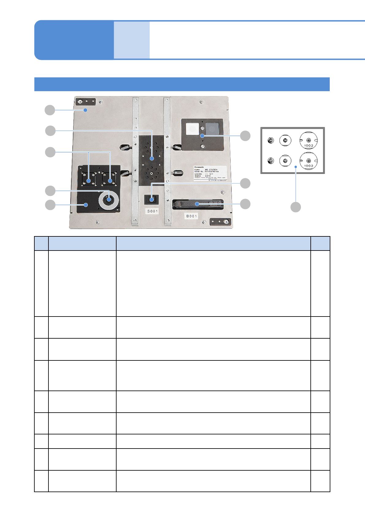
Jig station configuration
No.
Unit name Functions Q’ty
A Jig station
This is the unit used for head parameter calibration, for example,
when you replace the head. It can be shared by all the heads.
Power specifications: 12V DC (8 AA batteries) Prepare on your own.
(→P.12-3 Replacing the batteries)
Caution: If the batteries are left inside, they may leak; therefore,
if you do not use the jig station for a long period,
remove and store them.
Mass: 1.5kg Dimensions: 240mm (W) x 215mm (D) x 35mm (H)
1
B Jig components
Jig components used for calibration.
They are used by installing to the jig station.
2
C
Multi-recognition
camera LED
Light luminosity jig
Jig used for luminosity calibration of LED lighting on the multi-
recognition camera. It is used by installing to the jig station.
1
D Calibration nozzle
Nozzle used for calibration.
For 8-nozzle head: 184 nozzle
For 3-nozzle head: 1003 nozzle
2
each
E
Head camera LED
Light luminosity jig
The jig that is used in calibrating LED light’s luminosity on the head
camera is set to the place.
---
F Main power switch
When turning ON the power, green LED illuminates. (If not, replace
the battery)
---
G Photo sensor amplifier The sensor that detects jig components. ---
H Jig recognition section
It is used for recognition. Jig components are set to it when you
calibrate.
---
I Jig storage section
Jig components and light luminosity jig are set to this section before
calibration.
---
13-10-1
Maintenance
13-10
D
A
E
F
G
H
B
C
I
NPM-TT2 EJM1EE-MB-13M-02
Explains the jig station operating method, taking for an example, the 8-nozzle head; however, the same
procedure can also be applied to the 3-nozzle heads.
●Make sure that there are no nozzles present in the nozzle changer. Remove all the PCB support pins.
●If you cannot set a jig station, manually load the PCB from the pre-process machine and set the jig
using the workbench (please prepare yourself).
●Do not turn OFF the power of the machine during calibration.
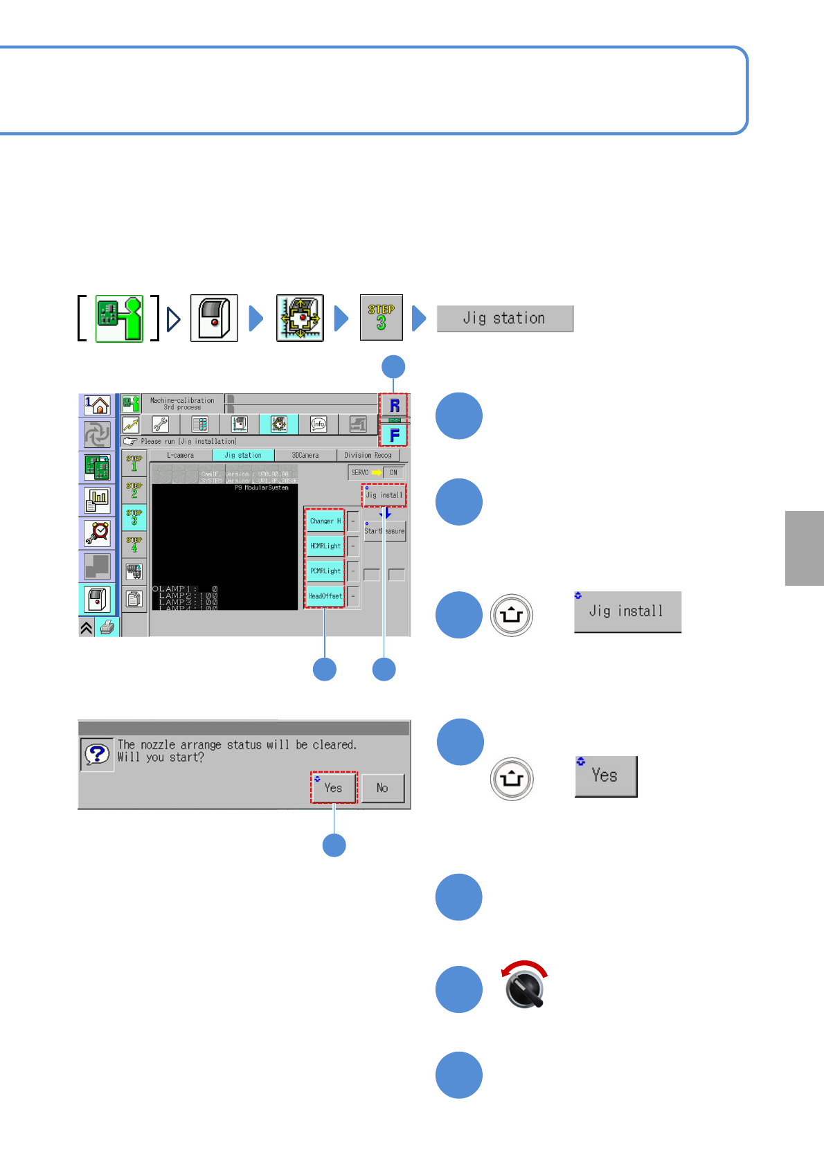
Choose a table
●Choose the table for calibration.
Choose a measurement item
(The selected items are displayed in
light blue color, and, all the rest, in gray)
+
13-10-2
3
1
2 3
2
1
Calibration
Open the safety cover
Prepare to install the jig
station
7
6
5
Servo switch OFF
4
4
(The width is adjusted)
(The head moves to the retraction
position)
Confirm the message
+
NPM-TT2 EJM1EE-MB-13M-02
13-10-3
Jig station 2
Maintenance
13-10
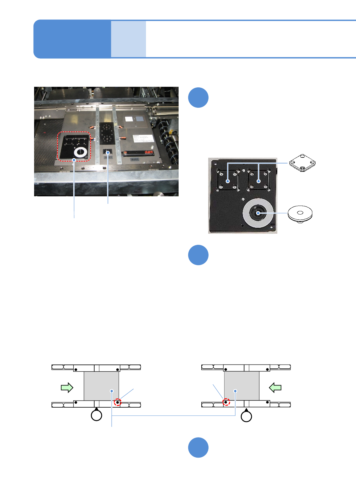
●Check that the LED lamp is
illuminated.
Turn ON the power of the jig
station
Place the jig station on the
transfer conveyor
●Align the end face of the jig station
with the reference mark on upper
surface of the front rail.
●Make sure to place it in the right
direction.
●If you cannot set a jig station,
manually load the PCB from the pre-
process machine and set the jig using
the workbench (please prepare
yourself).
●Left-to-right flow
Reference
mark
(φ1 hole)
Reference
mark
(φ1 hole)
●Right-to-left flow
Jig station
9
10
Set jig components and the
light luminosity jig to the jig
station
●Each of the two has no particular
orientation by itself.
Power supply
switch
Jig storage
unit
●Jig station
8
●Jig component, light and luminosity jig
storage unit
Light
luminosity jig
Jig components