N7201A653E.pdf - 第371页
NPM- TT2 EJ M1EE-MB-13M-0 2 13-10 -4 11 Calibration Open the safety cover Prepare to install nozzles (The head moves to the work position) 16 17 15 Close the safety cover + Confirm the message ■ To cancel (The screen rem…
NPM-TT2 EJM1EE-MB-13M-02
13-10-3
Jig station 2
Maintenance
13-10
●Check that the LED lamp is
illuminated.
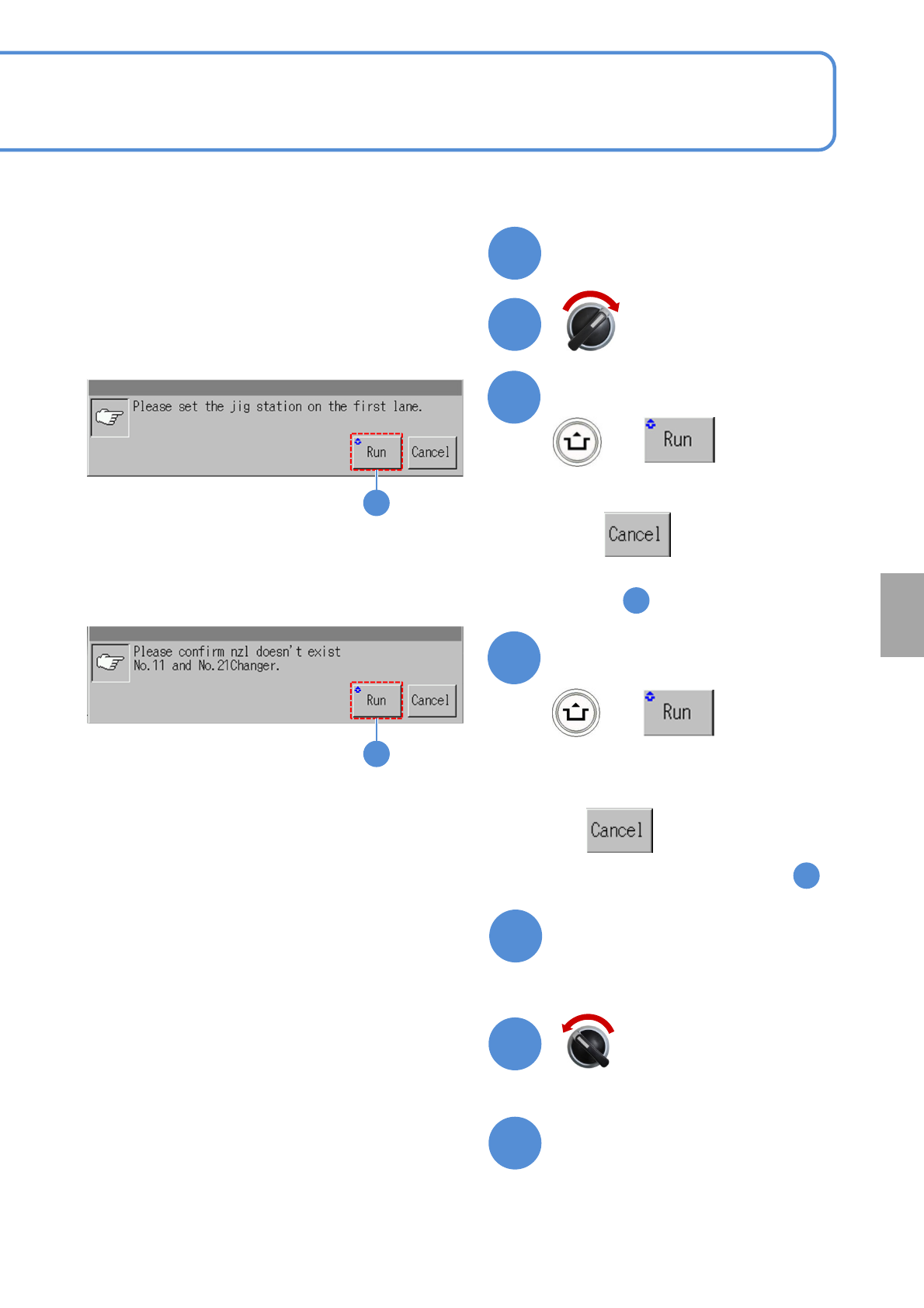
Turn ON the power of the jig
station
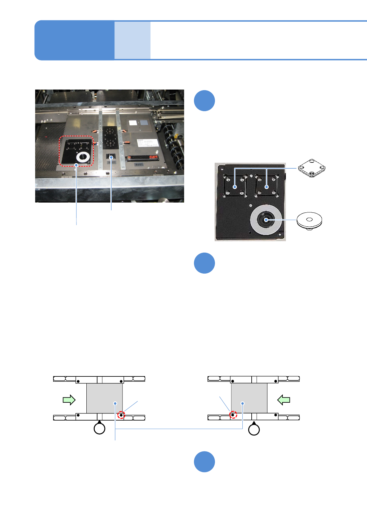
Place the jig station on the
transfer conveyor
●Align the end face of the jig station
with the reference mark on upper
surface of the front rail.
●Make sure to place it in the right
direction.
●If you cannot set a jig station,
manually load the PCB from the pre-
process machine and set the jig using
the workbench (please prepare
yourself).
●Left-to-right flow
Reference
mark
(φ1 hole)
Reference
mark
(φ1 hole)
●Right-to-left flow
Jig station
9
10
Set jig components and the
light luminosity jig to the jig
station
●Each of the two has no particular
orientation by itself.
Power supply
switch
Jig storage
unit
●Jig station
8
●Jig component, light and luminosity jig
storage unit
Light
luminosity jig
Jig components
NPM-TT2 EJM1EE-MB-13M-02
13-10-4
11
Calibration
Open the safety cover
Prepare to install nozzles
(The head moves to the work position)
16
17
15
Close the safety cover
+
Confirm the message
■To cancel
(The screen remains as it is
in )
12
13
2
13
Servo switch OFF
Servo switch ON
14
14
+
Confirm the message
■To cancel
(The screen remains as it is in )
2
NPM-TT2 EJM1EE-MB-13M-02
Jig station 3
13-10-5
Maintenance
13-10
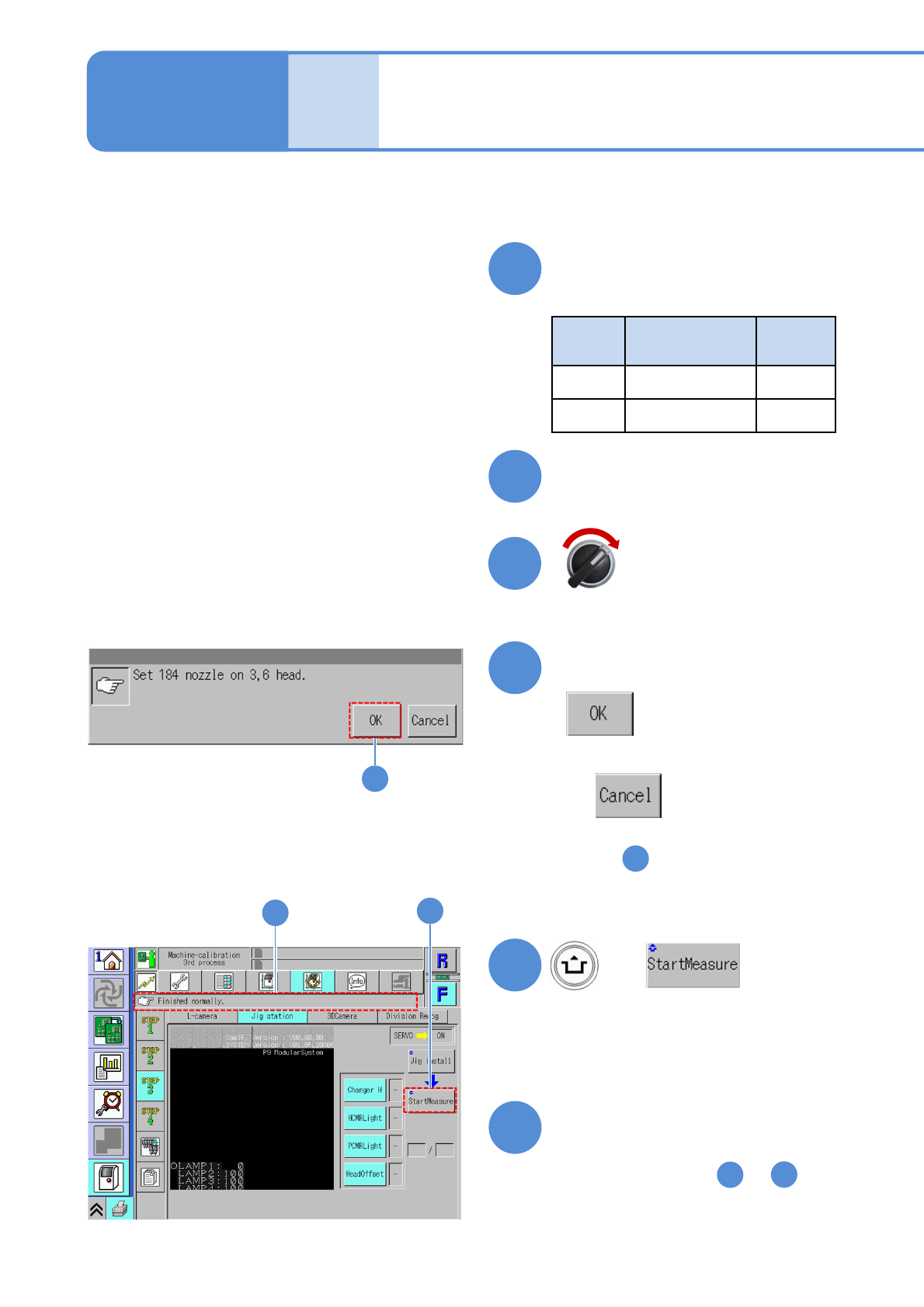
20
Confirm the message
■To cancel
(The screen remains as it is
in )
21
2
21
Confirm that it has been
successfully completed
●Repeat steps from to
from the other table.
23
1
23
(The selected measurement item is
calibrated)
22
23
22
+
Servo switch ON
Close the safety cover
Install nozzles
●Nozzle used
Head
type
Nozzle position
Nozzle
type
8 No. 3 and 6 184
3 No. 1 and 2 1003
18
19