N7201A653E.pdf - 第408页
NPM- TT2 EJM1EE-MB-13 M-02 3 13-15-2 -3 Detailed pr ocess 2 Accuracy verifica- tion Maintenance 13-15-2 Prepare the glass PCB Production preparation 3 (preparati on for verification material ) ① Prepare a glass PCB set (…
NPM-TT2 EJM1EE-MB-13M-02
2
1
To
Set the nozzles
to the nozzle
holders
(This task is the same as
the normal production
operation)
Place components
13-15-2-2
3
Offset Component to use Slot No.
Chip 1005JIG chip
Right side on
the 19th
Micro 0402R
Left side on
the 20th
Calibration
Production preparation 2 (preparation for verification material )
■For chip or micro
●Set a 1005JIG chip or 0402R to the tape feeder and install it
to the following slot.
●When placement is performed on the both heads (front and
rear), set the feeder on the front and rear sides.
●You should perform teaching of the pockets in the tape
feeder where appropriate.
(This task is the same as the normal production operation)
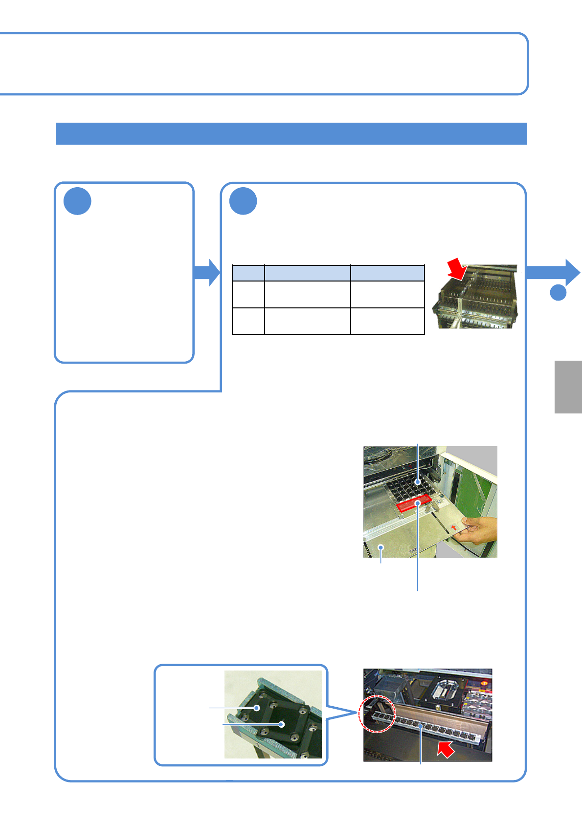
● Remove JIG_BGA (N610087876AA) from the tray and set it to the supply stage (N610074266AA).
● Left-align (Z1 to Z17) and install the supply stage.
●Install it in a line to prevent JIG_BGA from slanting.
●The supply stage consisting of two stages can be installed with 16 JIG_BGAs x 2 stages.
●Set a tray (storage aluminum case) to the slot 1 of the tray
feeder. (This task is the same as the normal production
operation)
●Install together with tray (storage aluminum case) to the
pallet.
●Right-align and set the tray (storage aluminum case) in the
back as seen from the rear.
●Pay attention to the installation orientation.
JIG_BGA itself has no particular orientation. However, do not
place any parts onto four boxes in the section A in the
picture on the right side.
●For the twin tray feeder, set it to slot 1 on the tray A side.
First stage
Second stage
Supply stage
■When JIG_BGA, supply stage is put on the feeder cart
2. When it is set to the feeder cart
1. When it is set to the tray feeder
Tray
(storage aluminum case)
Tray pallet
A section
NPM-TT2 EJM1EE-MB-13M-02
3
13-15-2-3
Detailed process 2
Accuracy
verifica-
tion
Maintenance
13-15-2
Prepare the glass PCB
Production preparation 3 (preparation for verification material )
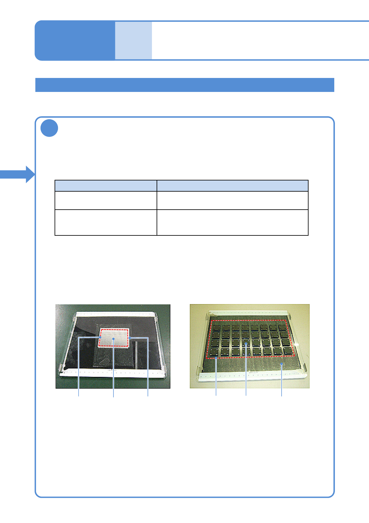
①Prepare a glass PCB set (N610108752AA) for placement accuracy check.
(Glass PCB, background plate and mirror are included)
Part Background
JIG_BGA Black sponge
(Set the background plate)
1005JIG chip: ERJJ02AAAAAV,
0402R, etc.
Insert a mirror between the glass and the
background plate.
(See the manual included in the glass PCB set)
●Affix the tape to the area where components are placed (Inside the dotted line in the picture
below is a rough area)
●Keep away from recognition marks on the both edges of the glass.
●Affix the tape with no air bubbles.
②Prepare the background based on a component to verify its accuracy.
③Affix the double-faced tape onto the glass PCB.
Glass PCB after 1005JIG chip are placed
Glass PCB after JIG_BGA are placed
MirrorPlacement
area
JIG_BGAPlacement
area
Background plate
(black sponge)
1005JIG
chip
NPM-TT2 EJM1EE-MB-13M-02
ACTIVATION
13-15-2-4
Calibration
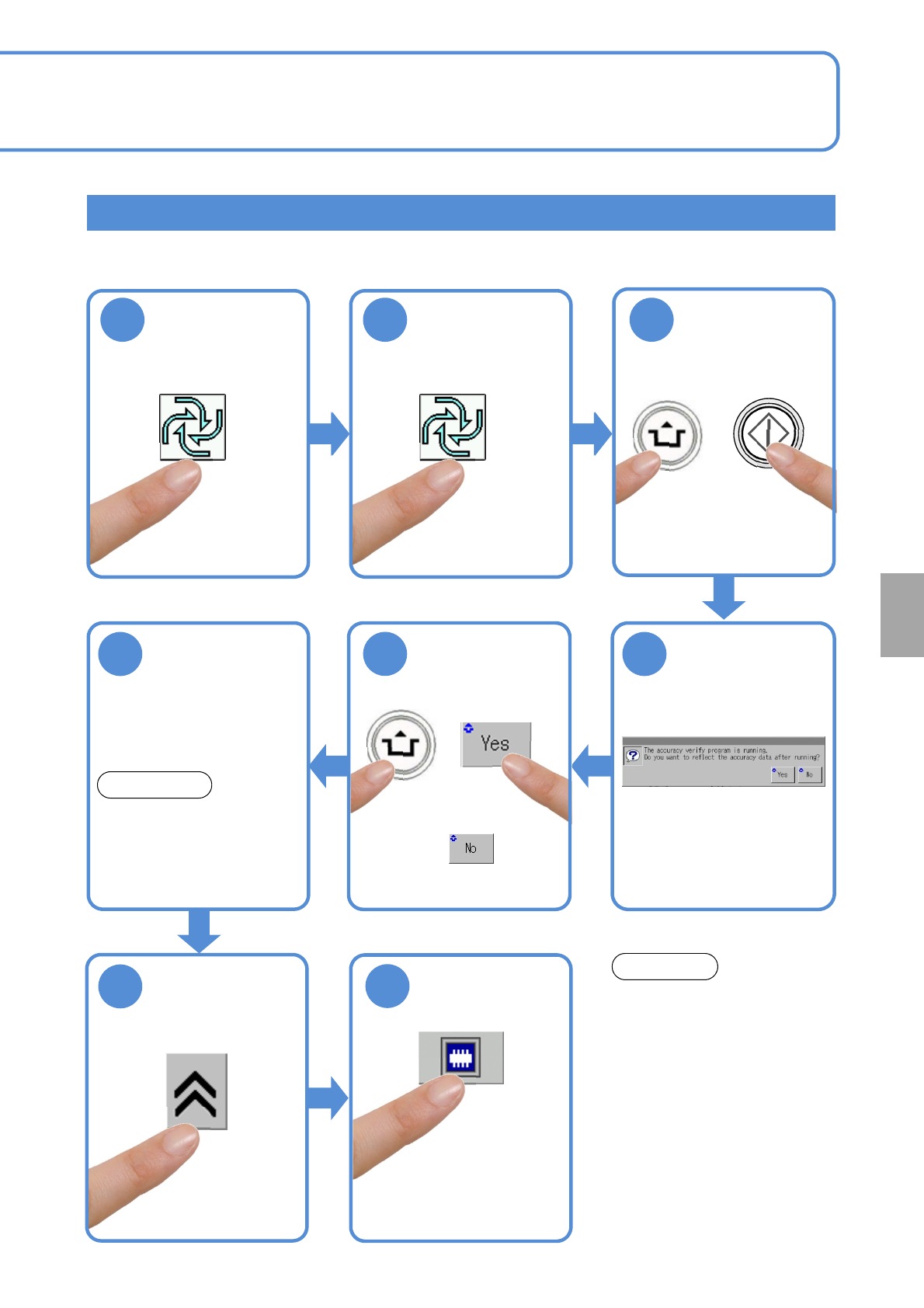
Checking and reflection of placement (placement)
321
(First layer)
(Second layer)
4
8
7
Do not press the STOP button
while accuracy verification is
carried out.
You cannot restart operation in
the middle of accuracy
verification.
NOTICE
6
Load glass PCB
●Production starts as the
glass PCB is loaded
upon completion of
production preparation.
If the machine is coupled to
another machine, adjust the PCB
width of the adjacent machine to
216 mm, and load the PCB into
the upstream machine.
NOTICE
Confirm the
message
5
●The head camera screen
appears and you can view
the part being measured.
●To use accuracy verification
MCDATA:
(→ P.13-15-1
-1 ‘■Reflection
of verification data’)
ACTIVATION