N7201A653E.pdf - 第418页
NPM- TT2 EJM1EE-MB-14 M-02 14-3 -1 Tool used: Convex, Allen wrench (3 mm, 4 mm), metal ruler, Level g auge, 65 mm spanners (2 pcs) Installa tion 1 Maintenance 14-3 1 Install Temporarily locate the machine along the basel…
NPM-TT2 EJM1EE-MB-14M-02
Transportation
14-2
Maintenance
14-2
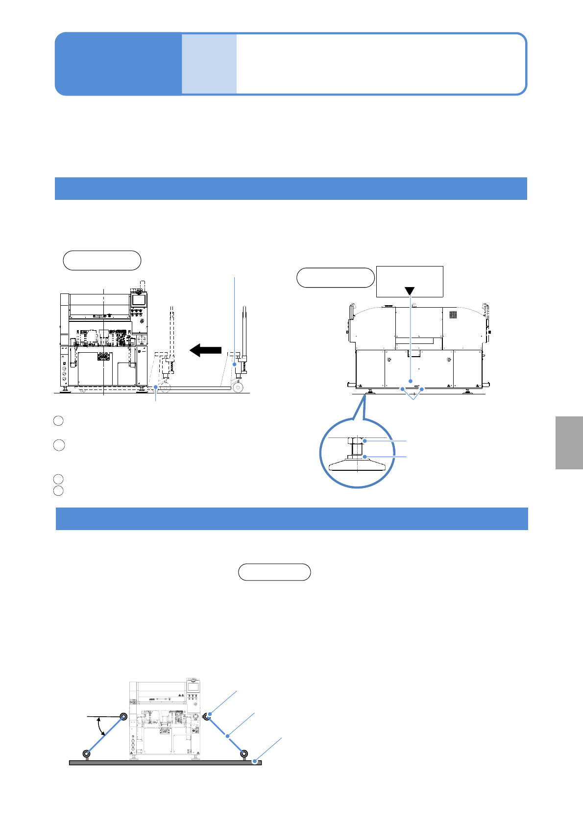
Using a forklift or a pallet truck
Handle the machine with extreme care when transporting.
The feeder cart and the tray feeder, if connected to the main body, should be removed before transportation.
In addition, for the machine with the extension conveyor installed, the cable attached to the conveyor must be
removed from the machine to prevent it from getting stuck by the fork.
Keep turning the adjustment bolt’s adjustment bolt until
the bottom of the machine is raised higher than the forks.
Insert the forks under the machine from the right side
(facing the front of the machine).
●Align the center of two forks to ▼ shown on the sticker.
Raise the forks and lift the machine.
Convey the machine to the destination and set it down.
Tool used: 65 mm spanner (2 pcs)
Pallet truck or forklift
Lock nut
Adjustment bolt
Fork insertion
position
Forks
■Fork insertion position
●Insert the forks from the side
Using a crane
Please consult a specialized delivery company.
Eye bolts
(four)
●Use eyebolts for fixing the machine to a cart or others. An angle
θ that the fixing rope makes with a horizontal line should be 45
degrees or less.
●Do not use eyebolts to lift the machine.
●Store eyebolts after transport.
ATTENTION
θ
Fixing rope
Cart
MASS:2650 kg
CENTER
1
2
3
4
Installation
Adjustment bolt
Front side
Right side
NPM-TT2 EJM1EE-MB-14M-02
14-3-1
Tool used: Convex, Allen wrench (3 mm, 4 mm), metal ruler, Level gauge, 65 mm spanners (2 pcs)
Installation 1
Maintenance
14-3
1
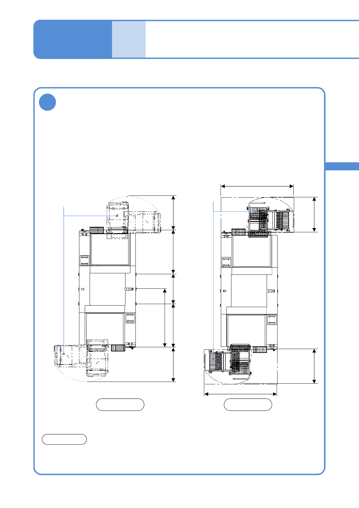
Install
Temporarily locate the machine along the baseline drawn on the floor and adjust the installation
position.
●Adjust the height and facing of the machine to guarantee a smooth PCB transfer between the
machine and adjacent equipment.
●Keep a 1 to 5 mm space between the machine and adjacent equipment.
●If running a vent under the machine, keep a 40 mm or more space between the machine and the
vent.
(The below figure shows the minimum space and is measured in millimeters (mm))
NOTICE
Front side
781
1 639
781
1 639
763
971
686
1 314
971
763
Feeder cart
(Option)
Single tray
feeder
(Option)
Front side
●Regarding installation, follow the instructions of a specialist.
●Regarding relocation, contact us, please.
NPM-TT2 EJM1EE-MB-14M-02
14-3-2
To
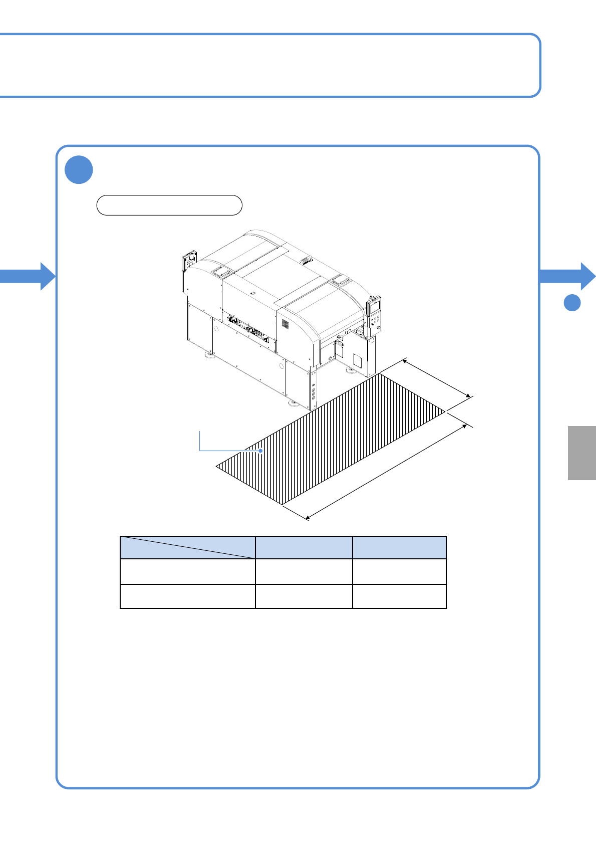
3
AB
Single tray feeder (Option) 763 1 831
Feeder cart (Option) 781 1 639
Check the working area
Front and rear sides
A
B
Working area
(Unit: mm)
Installation
2