N7201A653E.pdf - 第423页
NPM- TT2 EJM1EE-MB-14 M-02 14-3 -6 Installation Adjust the angle of the signal tow er 6 Adjust the angle and tighten the adjustment bolt. ● Recommended tightening torque: 3.0 N ・ m Signal tower: horizontally installed be…
NPM-TT2 EJM1EE-MB-14M-02
14-3-5
Maintenance
14-3
Installation 3
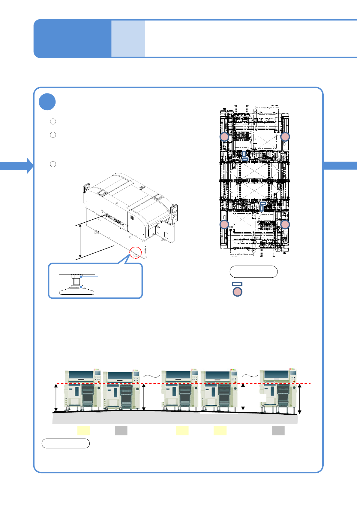
Level the machine
Place level gauges as shown in the right figure.
●Level: 4 locations
Level the machine with the adjustment bolts.
●The bubble should stay centered or within
3 division. (0.06 mm/m)
●4 adjustment bolts
Secure the adjustment bolts with the lock nuts.
You are recommended to check the level every six months after installation.
NOTICE
Level gauge installation sites
Adjustment bolts
PCB transfer
height
900 to 920 mm
1
2
3
Front side
Lock nut
Adjustment
bolt
■About PCB transfer height
●The standard PCB transfer height of NPM-TT2 is from 900 to 920 mm.
●If the PCB transfer heights of all your production-line NPM-TT2s cannot be 900 to 920 mm, please
consult our sales representative or customer service in advance.
●Depending on your plant floor conditions, the PCB transfer heights of your production-line machines
can vary as shown in the figure below, in which feeder carts may not be connected normally to
machines #2 and #15.
Floor
PCB
transfer
height
#1 #2 #7 #8 #15
NG NGOK OK OK
900mm
885mm
920mm
940mm
5
NPM-TT2 EJM1EE-MB-14M-02
14-3-6
Installation
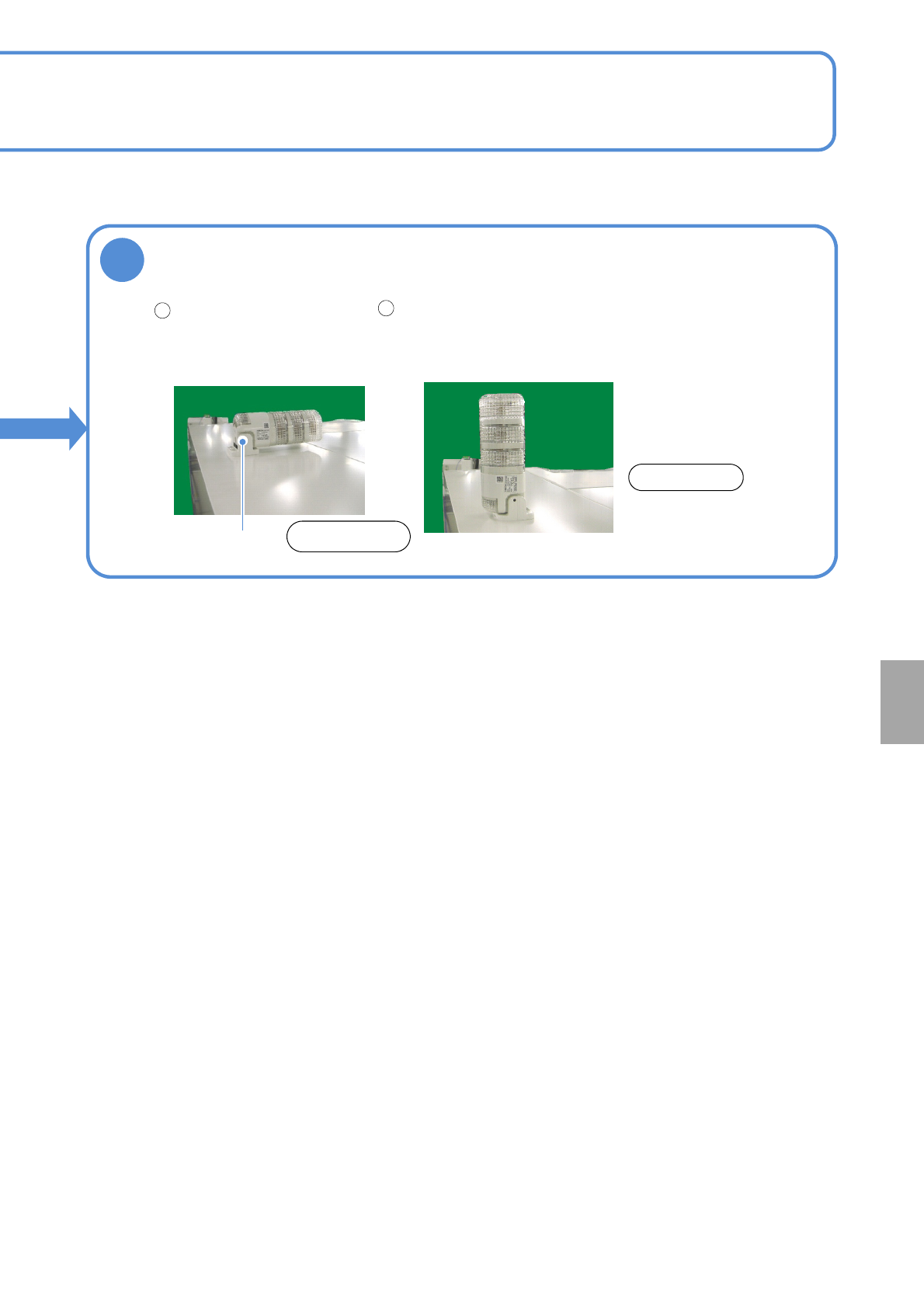
Adjust the angle of the signal tower
6
Adjust the angle and tighten the
adjustment bolt.
●Recommended tightening torque:
3.0 N・m
Signal tower:
horizontally installed
before shipment
Loosen the adjustment bolt
with Allen wrench (3 mm).
1
2
Adjustment bolt
NOTICE
Rear side
NPM-TT2 EJM1EE-MB-14M-02
Main
power
connec-
tion
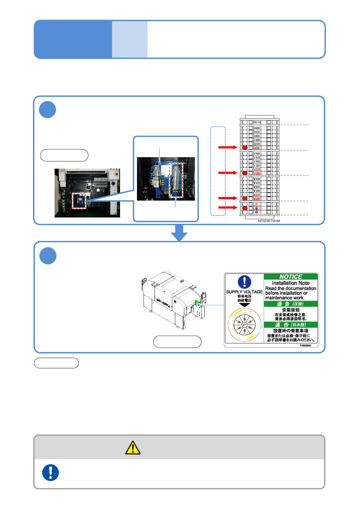
Checking voltages of the
primary power supply and
the machine
Maintenance
14-4-1
Ensure that the voltage setting of the machine is the same as that of the plant’s primary power supply.
●Before shipment, the voltage setting of the machine is configured as previously arranged with you.
Check the voltage indicated on the supply
voltage label
2
●Before using 290 V AC or
higher (any taps equal to or
higher than 380 V AC), ensure
that the voltage between a
ground and each phase is 290
V AC or lower and that star
connection is used on the
feeding side, with the N
(neutral) terminal connected to
the ground.
ATTENTION
●Before changing the primary input tap, make sure that the voltage after the tap change is the
same as the plant’s primary power-supply voltage. If not, the main transformer could generate
heat that causes the machine to malfunction.
●Separately use the breaker on the plant side. Before starting electrical construction, check the
specification for the rated power consumption and consult an electrical contractor. The shared
use of the breaker with other equipment may cause a fire due to heat generation.
●Even with the main power turned OFF, power is supplied up to the primary power line. Be careful
during maintenance work.
Front side
1
● Check the taps to which L10 cables are connected.
Grounding
earth
V:
Second phase
W:
Third phase
U:
First phase
■Wiring diagrams of transformer power
tap (abstract)
Transformer power
tap
Check the voltage of the transformer
power supply taps(Ex. for AC 200V)
Front side
Primary power voltage (factory side)
Transformer
●Even with the main power turned OFF, power is supplied up to the primary power line. Be careful
during maintenance work.
The power supply and the air source should be connected to the
machine at the end of installation
WARNING
14-4-1-1