N7201A653E.pdf - 第425页
NPM- TT2 EJM1EE-MB-14 M-02 Installation 14-4-1 -2
NPM-TT2 EJM1EE-MB-14M-02
Main
power
connec-
tion
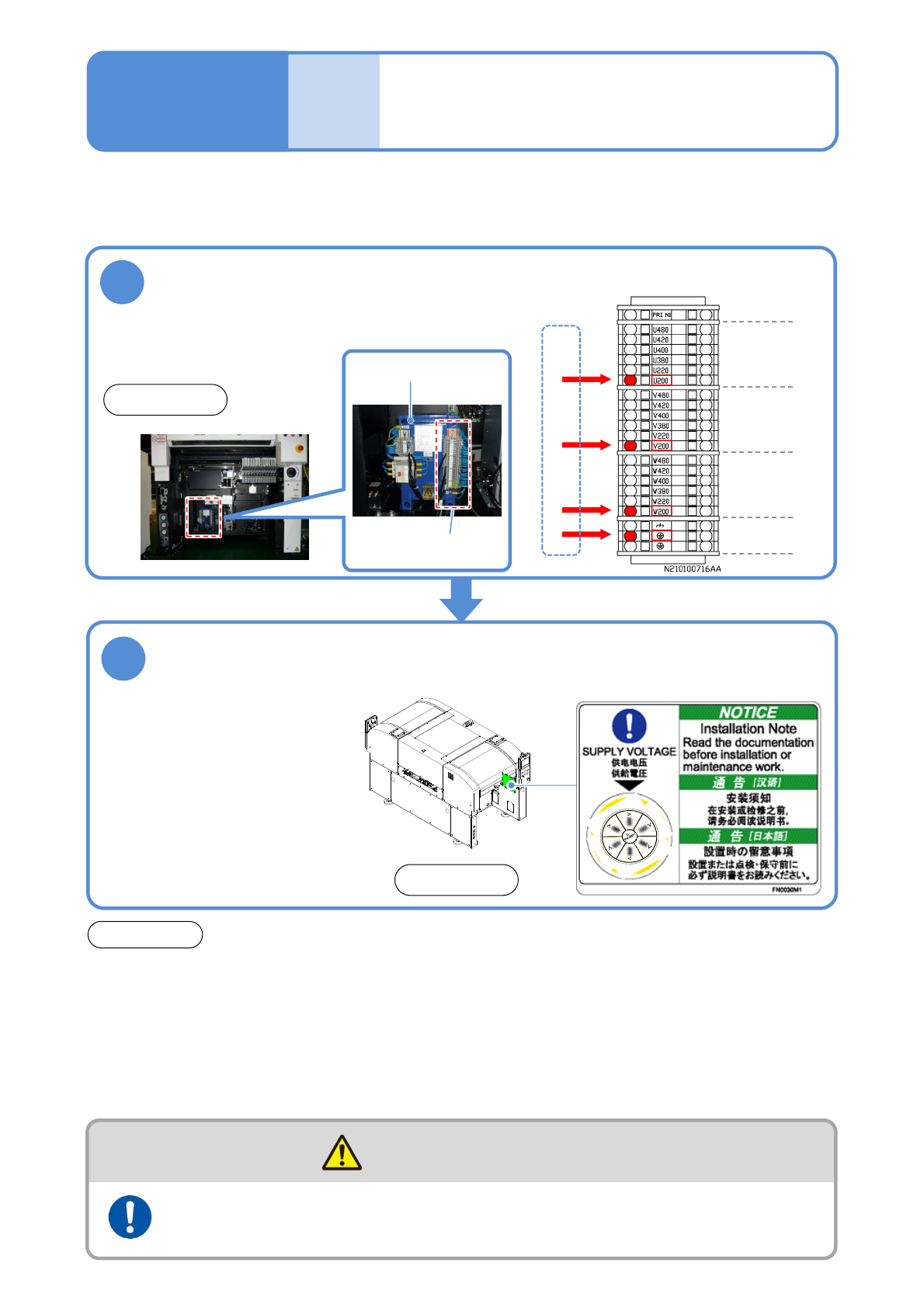
Checking voltages of the
primary power supply and
the machine
Maintenance
14-4-1
Ensure that the voltage setting of the machine is the same as that of the plant’s primary power supply.
●Before shipment, the voltage setting of the machine is configured as previously arranged with you.
Check the voltage indicated on the supply
voltage label
2
●Before using 290 V AC or
higher (any taps equal to or
higher than 380 V AC), ensure
that the voltage between a
ground and each phase is 290
V AC or lower and that star
connection is used on the
feeding side, with the N
(neutral) terminal connected to
the ground.
ATTENTION
●Before changing the primary input tap, make sure that the voltage after the tap change is the
same as the plant’s primary power-supply voltage. If not, the main transformer could generate
heat that causes the machine to malfunction.
●Separately use the breaker on the plant side. Before starting electrical construction, check the
specification for the rated power consumption and consult an electrical contractor. The shared
use of the breaker with other equipment may cause a fire due to heat generation.
●Even with the main power turned OFF, power is supplied up to the primary power line. Be careful
during maintenance work.
Front side
1
● Check the taps to which L10 cables are connected.
Grounding
earth
V:
Second phase
W:
Third phase
U:
First phase
■Wiring diagrams of transformer power
tap (abstract)
Transformer power
tap
Check the voltage of the transformer
power supply taps(Ex. for AC 200V)
Front side
Primary power voltage (factory side)
Transformer
●Even with the main power turned OFF, power is supplied up to the primary power line. Be careful
during maintenance work.
The power supply and the air source should be connected to the
machine at the end of installation
WARNING
14-4-1-1

NPM-TT2 EJM1EE-MB-14M-02
Installation
14-4-1-2
NPM-TT2 EJM1EE-MB-14M-02
Main
power
connec-
tion
Connection of the
main power supply
14-4-2-1
Maintenance
14-4-2
1
Prepare a cable and process terminals
Prepare four-core cable.
●Cross-section area:
3.5 to 5.5 mm
2
●Recommended sleeve
terminals
・Manufacturer:
PHOENIX CONTACT
・Type:
3.5-4.0 mm
2
Al4-12GY
5.5-6.0 mm
2
Al6-12YE
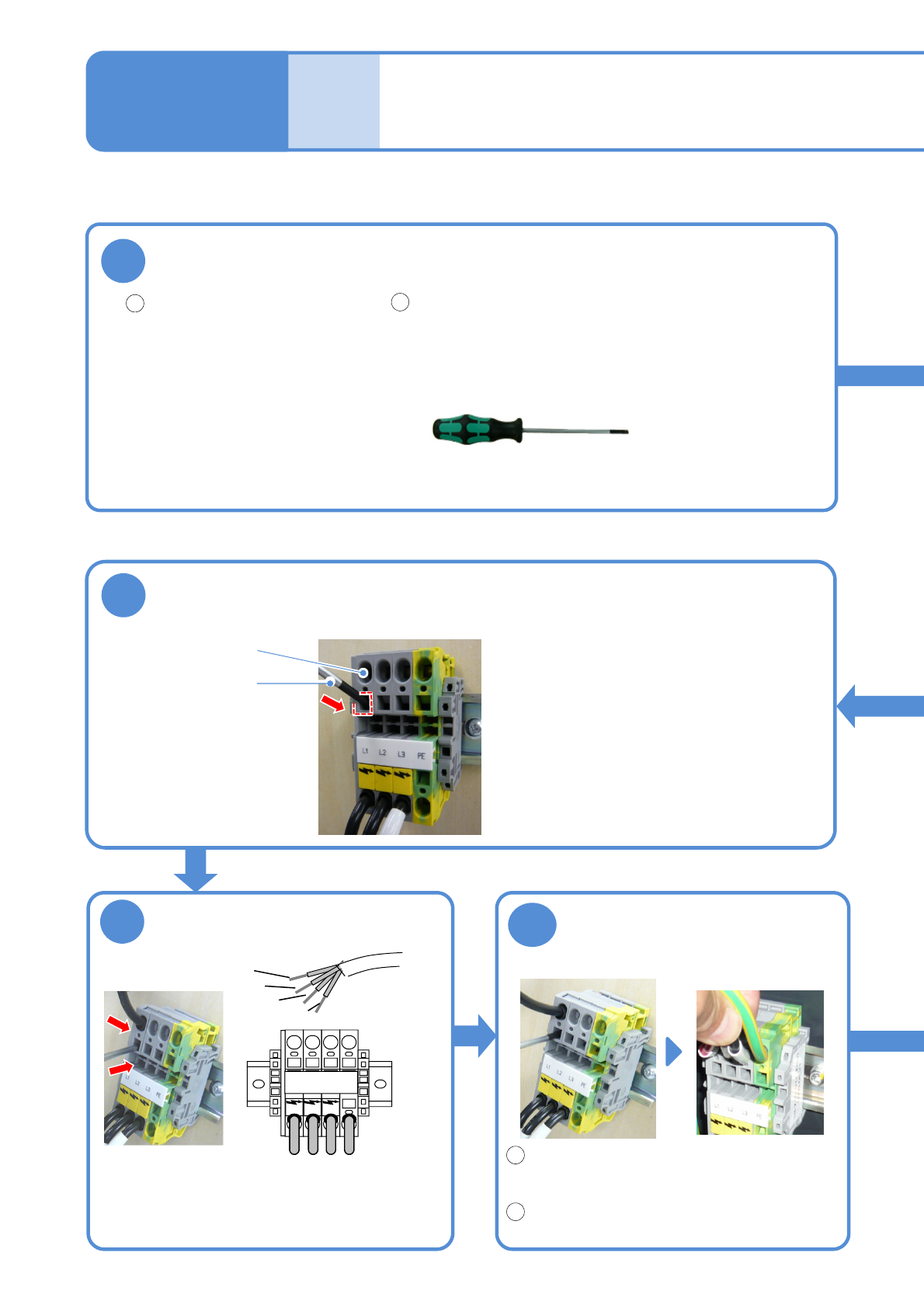
Tool used: Phillips screwdriver (No.2), special driver (provided)
Process the terminals to
be connected to the
machine.
Confirm secured insertions
Remove the special driver.
(The fixing bracket inside the cable insertion
slot closes)
Pull on the cable with a force of 50 N and
ensure that it is firmly-secured.
Insert the cable
Special driver (provided)
Insert the tip of cable
all the way to the end.
●Insert the sleeve terminals until their insulating
coatings go inside the terminal block.
●Connect the PE wire (green/yellow) first and then
connect the terminals in the order of L1→L2→L3.
■Main power terminal
Check the tension
1
2
1
2
6
5
4
L1 L2 L3 PE
L1
L2
L3
PE
Insert the special driver
Cable insertion slot
Special driver
●Insert the special driver deep enough to
open the fixing bracket inside the cable
insertion slot.
●Make sure that the PE wire on the plant
side is connected to ground.