N7201A653E.pdf - 第426页
NPM- TT2 EJ M1EE-MB-14M-0 2 Main power connec- tion Connection of the main po wer supply 14-4-2 -1 Maintenance 14-4-2 1 Prepare a cable and process terminals Prepare four-core cable. ● Cross-section area: 3.5 to 5.5 mm 2…

NPM-TT2 EJM1EE-MB-14M-02
Installation
14-4-1-2
NPM-TT2 EJM1EE-MB-14M-02
Main
power
connec-
tion
Connection of the
main power supply
14-4-2-1
Maintenance
14-4-2
1
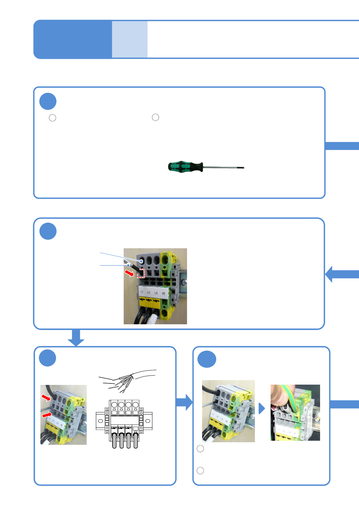
Prepare a cable and process terminals
Prepare four-core cable.
●Cross-section area:
3.5 to 5.5 mm
2
●Recommended sleeve
terminals
・Manufacturer:
PHOENIX CONTACT
・Type:
3.5-4.0 mm
2
Al4-12GY
5.5-6.0 mm
2
Al6-12YE
Tool used: Phillips screwdriver (No.2), special driver (provided)
Process the terminals to
be connected to the
machine.
Confirm secured insertions
Remove the special driver.
(The fixing bracket inside the cable insertion
slot closes)
Pull on the cable with a force of 50 N and
ensure that it is firmly-secured.
Insert the cable
Special driver (provided)
Insert the tip of cable
all the way to the end.
●Insert the sleeve terminals until their insulating
coatings go inside the terminal block.
●Connect the PE wire (green/yellow) first and then
connect the terminals in the order of L1→L2→L3.
■Main power terminal
Check the tension
1
2
1
2
6
5
4
L1 L2 L3 PE
L1
L2
L3
PE
Insert the special driver
Cable insertion slot
Special driver
●Insert the special driver deep enough to
open the fixing bracket inside the cable
insertion slot.
●Make sure that the PE wire on the plant
side is connected to ground.
NPM-TT2 EJM1EE-MB-14M-02
Cable
clamp A
14-4-2-2
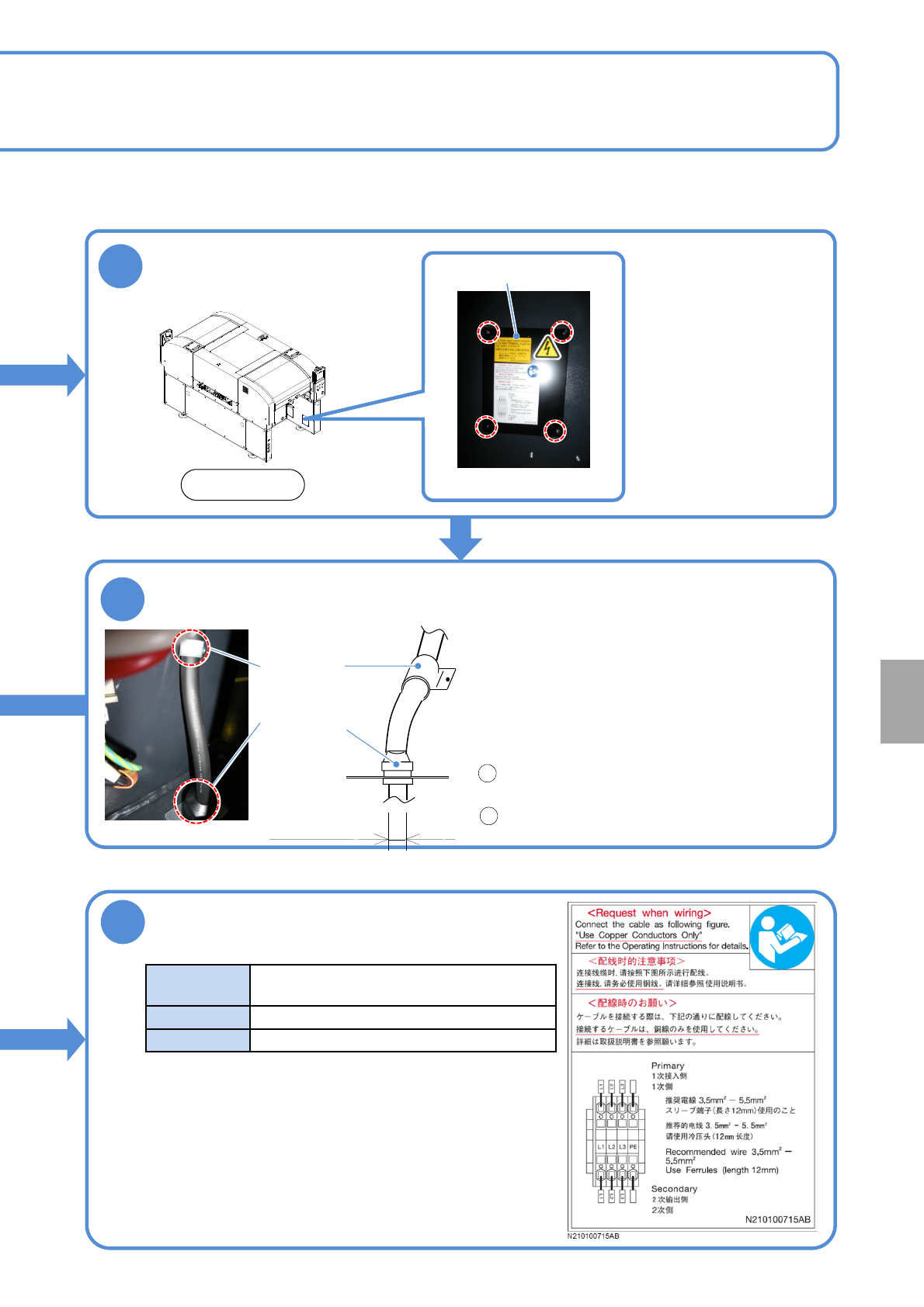
3
Pass the cable through cable clamps A and B, in that order
Cable
clamp B
●Recommended cable external dimensions:
13.5 to 18mm
●If you have trouble passing the cable through
Cable clamp A, loosen the clamp by turning it
counterclockwise.
●If you have trouble passing the cable through
Cable clamp B, pass the cable after removing the
mounting bolt and then bolt it again.
After passing the cable through Cable clamp A,
secure it by turning the clamp clockwise.
Pull on the cable with a force of 100 N and
ensure that the cable is firmly-secured.
7
Check the following conditions before
turning on the power
Ordinary use
power source
3-phase AC 200/220 ±10 V
380/400/420/480 ±20 V
Frequency
50/60 Hz ±5 %
Rating capacity
2.5 kVA
The primary power should be supplied from power-supply
facilities controlled inside your plant, rather than establishing
a direct connection with the public low-voltage power
distribution system (commercial power).
Recommended
cable external
dimensions
1
2
Remove the front
right side cover
Front side
2
Cover
●Four bolts
Installation