N7201A653E.pdf - 第431页
NPM- TT2 EJ M1EE-MB-14M-0 2 1 14-5 -2 Checking the power connection 3 Check the vacuum state ● The system is designed to check the phase of the vacuum-pump motor automatically as the power is turned on. ● If an error mes…
NPM-TT2 EJM1EE-MB-14M-02
Connection of air source
and power supply
Maintenance
14-5
14-5-1
Tool used: Phillips screwdriver (No. 2), Allen wrench (3 mm)
3
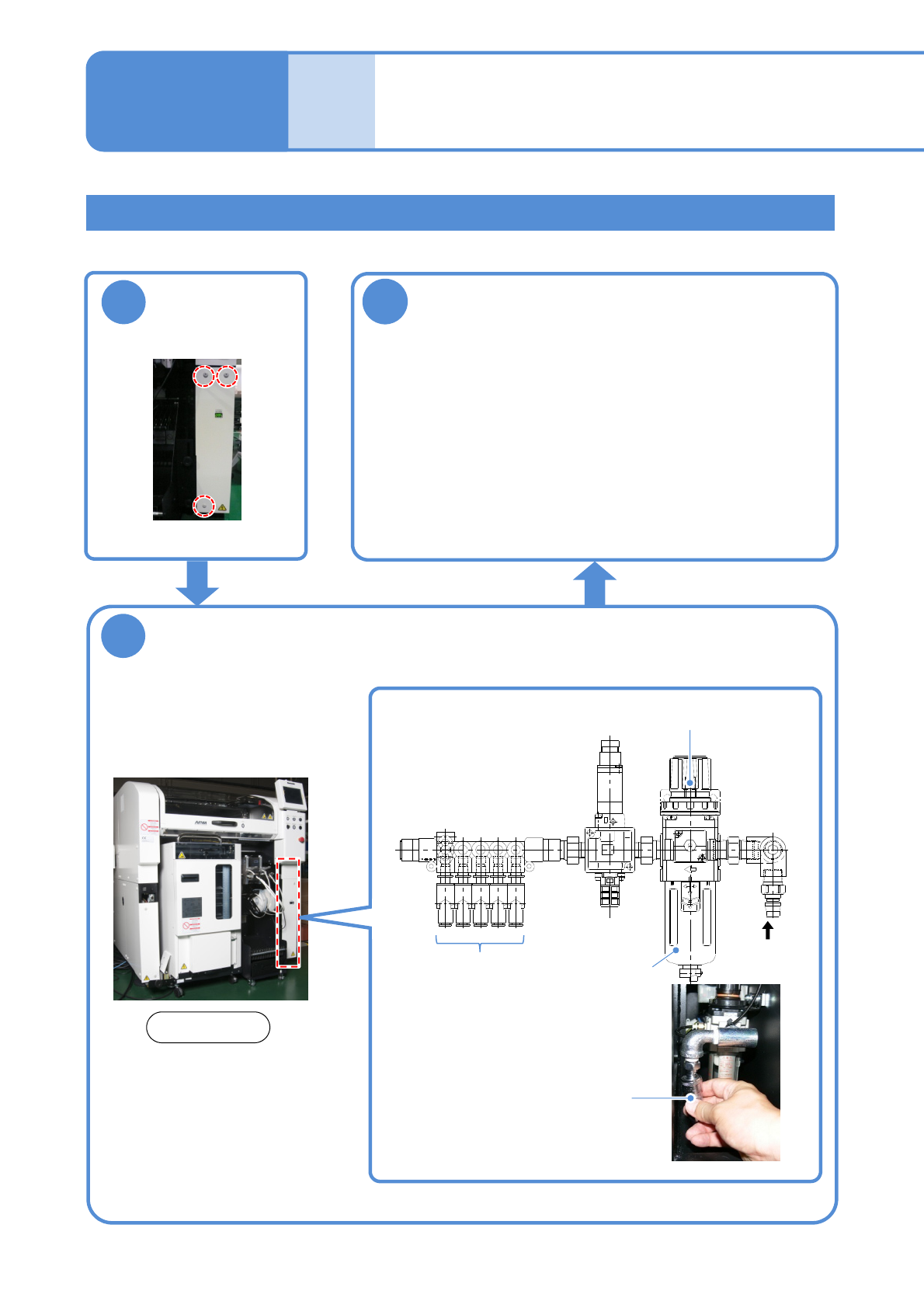
Supply air
●Use an air dryer and always supply clean air.
●Air pressure: 0.5 to 0.8 MPa
(The size of the inlet for connecting the hose is 3/8)
●After supplying air, adjust the air pressure to 0.500 to
0.505 MPa with the regulator (→P.4-1
-1)
●Air supply rate: 200 L/min (A.N.R.)
2
Connect the compressed air piping to the
area A in the figure below
Connecting air source
Compressed air piping
(Primary air supply side)
To each
device
A
Filter (inside)
1
Rear side
●Bolts (3 pcs)
Regulator
Detach the cover
on the right rear
side
NPM-TT2 EJM1EE-MB-14M-02
1
14-5-2
Checking the power connection
3
Check the
vacuum state
●The system is designed
to check the phase of
the vacuum-pump motor
automatically as the
power is turned on.
●If an error message is
displayed, confirm the
error information and
check if each phase of
the primary power
source is connected.
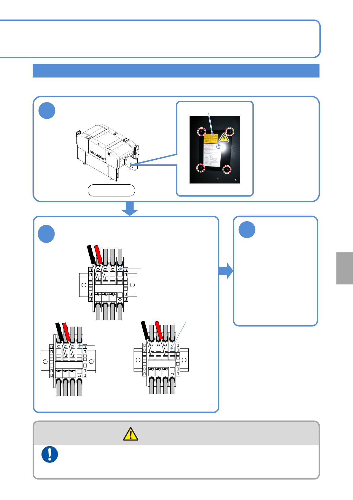
Remove the front
right side cover
An incorrect main power connection may reverse and damage the vacuum pump. Check to see if it is
correctly connected.
Connect the power supply and the air source to the machine at
the end of installation after checking for the voltage and
connections
(Risk of electric shock)
WARNING
Cover
●Four bolts
Front side
L1 L2 L3 PE
2
Make sure that voltage on the following three
parts is the same as shown on the supply
voltage label (→P.13-4-3).
L1 L2 L3 PE
L1 L2 L3 PE
Main power
terminals
Checking for voltage
between L1 and L2
Main
power
terminals
Checking for voltage
between L2 and L3
Checking for voltage
between L1 and L3
Main
power
terminals
Installation
NPM-TT2 EJM1EE-MB-14M-02
Peripher-
al device
connec-
tion
Line configuration
14-6-1
Maintenance
14-6-1
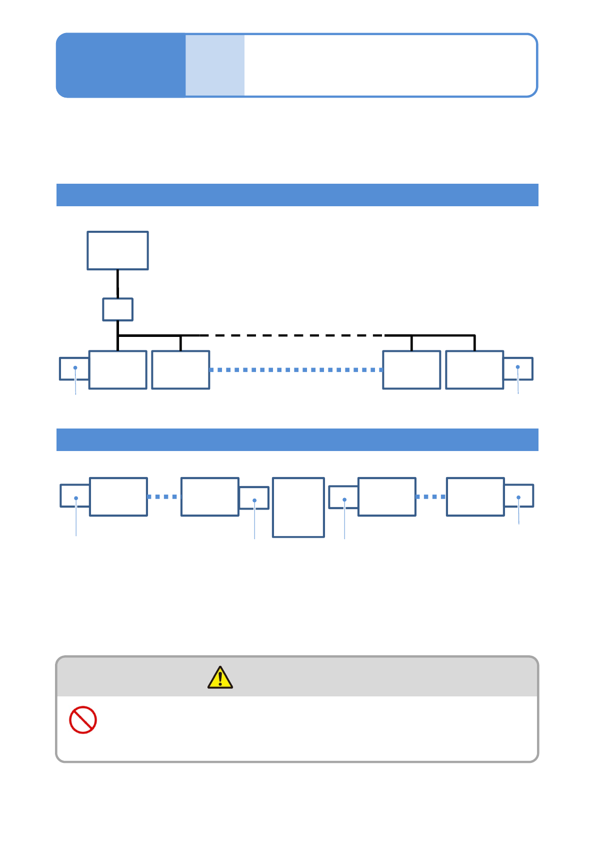
Extension conveyor
This is a sample line configuration, so it can vary depending on your line configuration and
the position of in-line non-NPM.
For details, please contact us.
To install NPM-TT2 (as a stand-alone unit or in-line), the installation of a unit that functions as an extension
conveyor (option) is required at both ends of the NPM-TT2 line.
●Up to 30 NPM-TT2s can be coupled together.
When the cable attached to the extension conveyor (optional item specified by us) is not plugged to the
machine, plug it.
Line configuration including NPM-TT2s only
Line configuration including NPM-TT2s and other than NPM-D
FA
computer
for LNB
HUB
NPM-TT2
1
NPM-TT2
2
Extension conveyor
NPM-TT2
29
NPM-TT2
30
Conveyor L
NPM-D
1
NPM-TT2
Extension conveyor
NPM-TT2
NPM-TT2
30
Other
than
NPM-TT2
Extension conveyor
Extension conveyor
■Up to 30 machines can be coupled with NPM-TT2 and NPM-D all together
■Up to 30 NPM-TT2s can be coupled together
The power supply and the air source must be connected to the
machine after installation of peripheral equipment
(Risk of electric shock or injury)
WARNING