N7201A653E.pdf - 第432页
NPM- TT2 EJ M1EE-MB-14M-0 2 Peripher- al device connec- tion Line configur a tion 14-6-1 Maintenance 14-6-1 Extension conveyor This is a sample line configu ration, so it can vary depe nding on your line configuration an…
NPM-TT2 EJM1EE-MB-14M-02
1
14-5-2
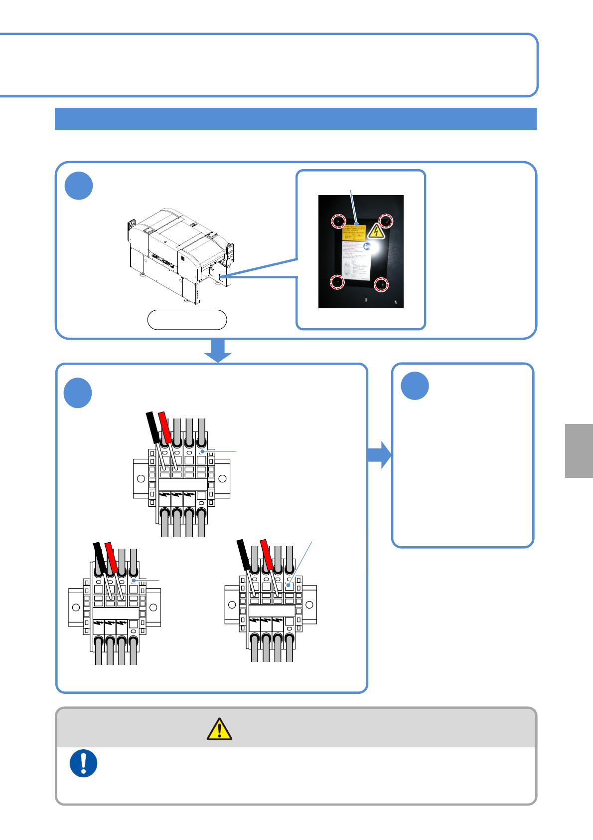
Checking the power connection
3
Check the
vacuum state
●The system is designed
to check the phase of
the vacuum-pump motor
automatically as the
power is turned on.
●If an error message is
displayed, confirm the
error information and
check if each phase of
the primary power
source is connected.
Remove the front
right side cover
An incorrect main power connection may reverse and damage the vacuum pump. Check to see if it is
correctly connected.
Connect the power supply and the air source to the machine at
the end of installation after checking for the voltage and
connections
(Risk of electric shock)
WARNING
Cover
●Four bolts
Front side
L1 L2 L3 PE
2
Make sure that voltage on the following three
parts is the same as shown on the supply
voltage label (→P.13-4-3).
L1 L2 L3 PE
L1 L2 L3 PE
Main power
terminals
Checking for voltage
between L1 and L2
Main
power
terminals
Checking for voltage
between L2 and L3
Checking for voltage
between L1 and L3
Main
power
terminals
Installation
NPM-TT2 EJM1EE-MB-14M-02
Peripher-
al device
connec-
tion
Line configuration
14-6-1
Maintenance
14-6-1
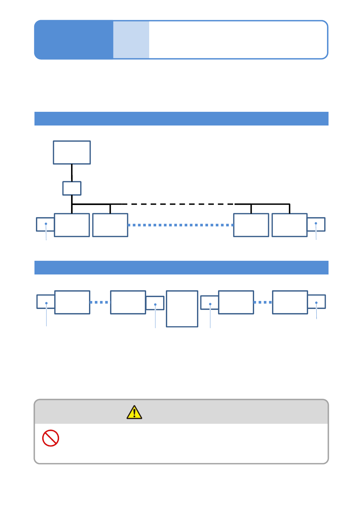
Extension conveyor
This is a sample line configuration, so it can vary depending on your line configuration and
the position of in-line non-NPM.
For details, please contact us.
To install NPM-TT2 (as a stand-alone unit or in-line), the installation of a unit that functions as an extension
conveyor (option) is required at both ends of the NPM-TT2 line.
●Up to 30 NPM-TT2s can be coupled together.
When the cable attached to the extension conveyor (optional item specified by us) is not plugged to the
machine, plug it.
Line configuration including NPM-TT2s only
Line configuration including NPM-TT2s and other than NPM-D
FA
computer
for LNB
HUB
NPM-TT2
1
NPM-TT2
2
Extension conveyor
NPM-TT2
29
NPM-TT2
30
Conveyor L
NPM-D
1
NPM-TT2
Extension conveyor
NPM-TT2
NPM-TT2
30
Other
than
NPM-TT2
Extension conveyor
Extension conveyor
■Up to 30 machines can be coupled with NPM-TT2 and NPM-D all together
■Up to 30 NPM-TT2s can be coupled together
The power supply and the air source must be connected to the
machine after installation of peripheral equipment
(Risk of electric shock or injury)
WARNING
NPM-TT2 EJM1EE-MB-14M-02
Peripher-
al device
connec-
tion
Line signal
specifications 1
14-6-2-1
Maintenance
14-6-2
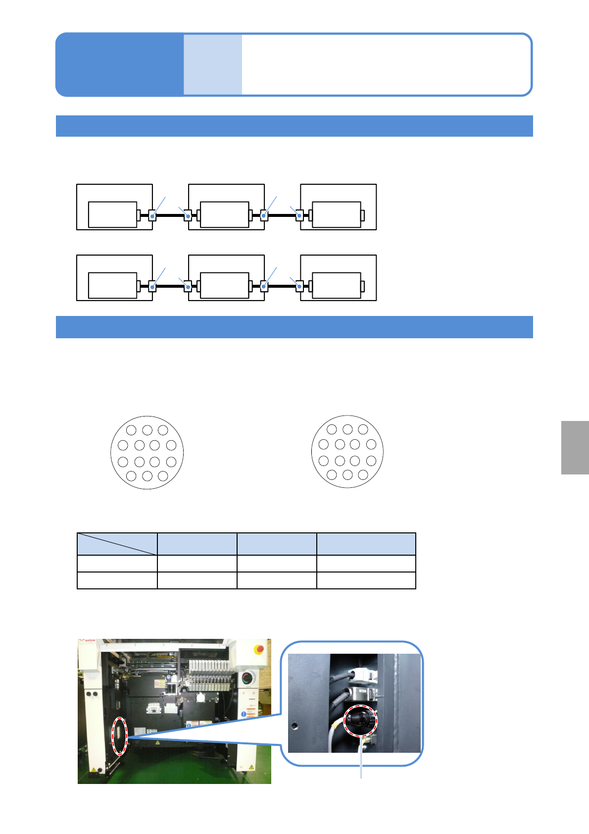
Line signals
A single cable connection is established throughout a line, allowing one machine in line to signal it’s
connecting machine to transfer PCBs.
1
2
3
47
8
11
14
13
12
3
2
1
74
11
8
12
13
14
SMEMA connectors are AMP-type connectors for easy connection.
■Connector pin arrangements as seen from the connection ports
Cable-side connector pin arrangement
(Male pins)
Connector Pin Strain relief
Cable side
AMP 206044-1 AMP 66103-2 AMP206070-1
Machine side
AMP 206043-1 AMP 66105-2 -
■Part numbers on the cable and the machine sides
■ SMEMA connector location (one on either side of the rear of the machine)
Arrangement of connector pins
SMEMA connector
Machine-side connector pin arrangement
(Female pins)
Installation
-XS
Connector connected to the next
process machine
-XP
Connector connected to the pre-
process machine
Machine 1
Control
Box
Machine 2
Control
Box
Machine 3
Control
Box
-XP
-XS
-XP
-XS
■PCB flow direction (From right to left)
Machine 3
Control
Box
Machine 2
Control
Box
Machine 1
Control
Box
-XS
-XP
-XS
-XP
■PCB flow direction (From left to right)