N7201A653E.pdf - 第435页
NPM- TT2 EJ M1EE-MB-14M-0 2 Peripher- al device connec- tion Ether net cables LW S (line wo r k station) 14-6-3 Maintenance 14-6-3 The result data accumu lated in LNB can be displayed on LWS (Lin e Work Station) by estab…
NPM-TT2 EJM1EE-MB-14M-02
Peripher-
al device
connec-
tion
Line signal
specifications 2
14-6-2-2
Maintenance
14-6-2
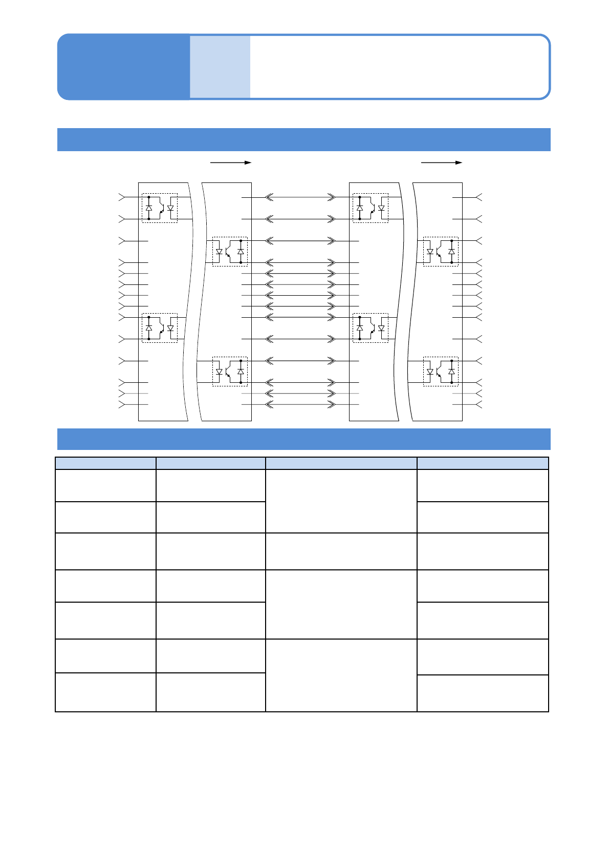
Electrical-interface wiring diagram (SMEMA interface)
Connector/Cable Function Conditions Explanation
Pair 1-2
1)
Machine preparation
Close
2) 3)
Device that receives the
next PCB (single conveyor)
Pair 3-4
1)
PCB valid
Device that has a PCB to
send(single conveyor)
Pair 5-6 / 7-8
4)
Inter-device state
output/input
Available only when devices
are connected adjacent to each
other
Input and output of the
status between devices
Pair 9-10 Machine preparation
Close
2) 3)
Device that receives the
next PCB (dual conveyor)
Pair 11-12 PCB valid
Device that has a PCB to
send
(dual conveyor)
13
4)
Inter-device safety
device input
Available only when devices
are connected adjacent to each
other
Status of safety device
between devices (input)
14
4)
Inter-device transfer
sensor state input
Status of transfer sensor
connected adjacently
1)
As a minimum requirement, switch to 10 mA and 30 V DC. (For the single conveyor)
2)
Prevent the output LOW or Contact Close from exceeding 0.8 V DC under the condition of 10 mA.
3)
When using the optical isolator, check for the appropriate polarity.
4)
This is a signal used exclusively between NPM machines. You cannot input external signals.
●Existing devices that are not assembled based on this standard may need a fixed pin arrangement.
1
2
3
4
5
6
7
8
9
10
11
12
13
14
1
2
3
4
5
6
7
8
9
10
11
12
13
14
CONN.1
(-XP)
CONN.2
(-XS)
1
2
3
4
5
6
7
8
9
10
11
12
13
14
1
2
3
4
5
6
7
8
9
10
11
12
13
14
CONN.1
(-XP)
CONN.2
(-XS)
BOARD BOARD
L1 MACHINE
READY
L1 BOARD
AVAILABLE
L2 MACHINE
READY
L2 BOARD
AVAILABLE
L1 MACHINE
READY
L1 BOARD
AVAILABLE
L2 MACHINE
READY
L2 BOARD
AVAILABLE
L1 MACHINE
READY
L1 BOARD
AVAILABLE
L2 MACHINE
READY
L2 BOARD
AVAILABLE
MACHINE B
MACHINE A
Functional descriptions of electrical-interface connectors/cables
NPM-TT2 EJM1EE-MB-14M-02
Peripher-
al device
connec-
tion
Ethernet cables
LWS
(line work station)
14-6-3
Maintenance
14-6-3
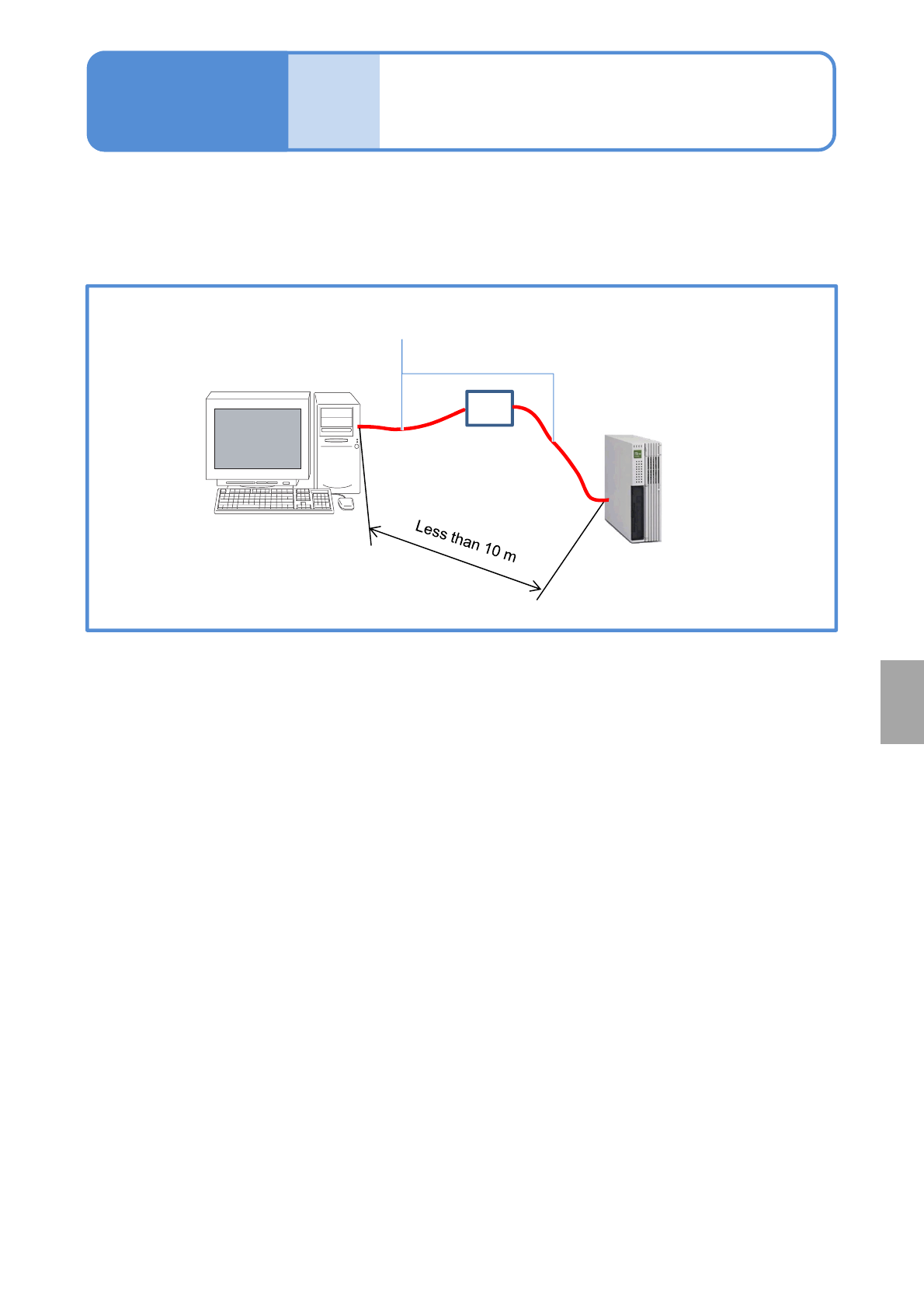
The result data accumulated in LNB can be displayed on LWS (Line Work Station) by establishing an
Ethernet cable connection between your PC and a PC intended for LNB use. No installation of dedicated
software is required for the PC, but Web browser is required. For details, please refer to the LNB instruction
manual.
Ethernet cable
If the cable is longer
than 10 m, contact us.
PC (LWS)
FA PC for LNB
HUB
Installation
NPM-TT2 EJM1EE-MB-14M-02
Peripher-
al device
connec-
tion
Cable length
14-6-4
Maintenance
14-6-4
Items that need to be connected:
●Line signal (insulated)
1)
●AC (alternating current) power source
1) The machine system and the system of ancillary equipment are already insulated.
The power source or the line signal cables that correspond to line configuration can vary depending on
your specifications. So, please contact us.
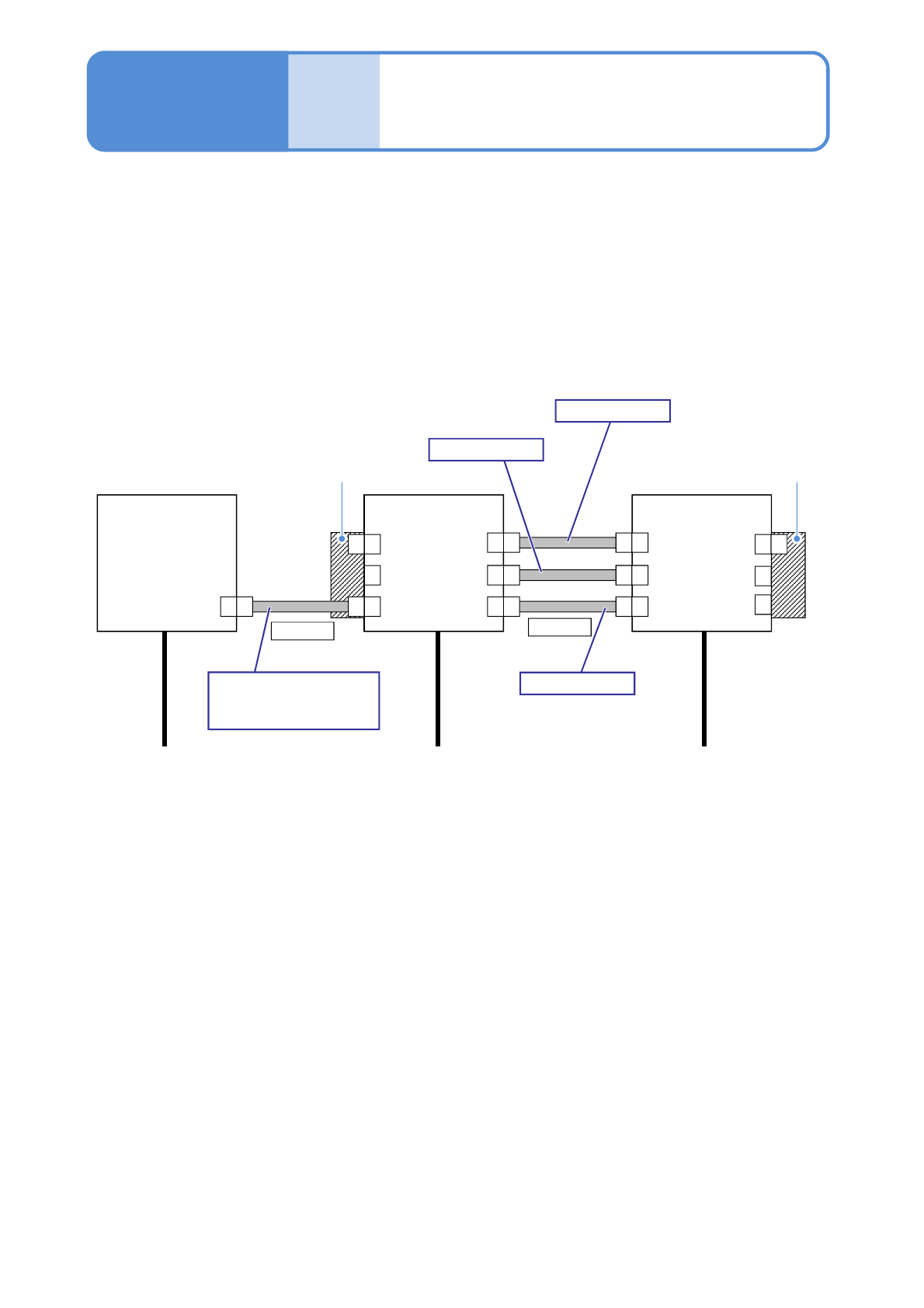
■Line configuration Example: conventional machine support
FM MF
F
F
SMEMA
Power
L1,L2,L3,PE
Power
L1,L2,L3,PE
Power
L1,L2,L3,PE
Conventional
machine
NPM-TT2
NPM-TT2
2 m
Regarding connection
other than the NPM-TT2,
please ask us.
SMEMA
FM MF
FM MF
FM MF
-XP -XS
CNDUS
CNEXR
-XP
CNDUP
CNEXL
-XS
N610129393AB
2 m
N610129395AB
2 m
N610129394AB
Extension conveyor Extension conveyor
MF
F
MF