N7201A653E.pdf - 第448页
NPM- TT2 EJ M1EE-MB-14M-0 2 14-9 -3 Maintenance 14-9 Ho w to s witch the 17-slot f eeder car t and the single tr ay f eeder 2 ① Switching the single tray feed er to the 17-slot feeder cart 1 This explains how to switch b…
NPM-TT2 EJM1EE-MB-14M-02
14-9-2
Installation
Installation location
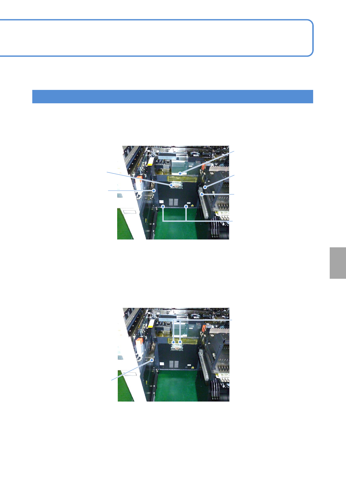
This explains the installation location of the units used for switching.
For details, see the switch procedure described later.
(d) Safety cover
(Feeder cart)
(e) Extension drawer
(Feeder cart)
(a) Cart drive unit
(Feeder cart)
(f) Grommet
(Feeder cart)
(b) Drive guide
(Feeder cart)
■Installation location of the units used for feeder cart switch
■Installation location of the units used for tray feeder switch
(f) M6 screw
(Tray feeder)
(Short connector
(Tray feeder)
(c) Cart guide
(Feeder cart)
NPM-TT2 EJM1EE-MB-14M-02
14-9-3
Maintenance
14-9
How to switch the 17-slot
feeder cart and the single
tray feeder 2
①Switching the single tray feeder to the 17-slot feeder cart 1
This explains how to switch between the 17-slot feeder cart and the single tray feeder.
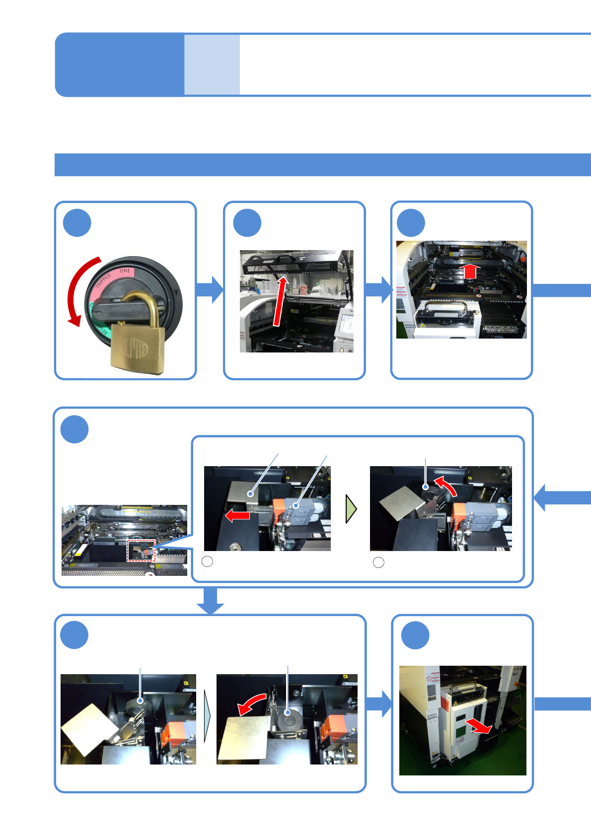
Time required: 30 minutes
Tool used: Spanner 30 mm (2), Allen wrench (3 mm, 4 mm, 5 mm, 8 mm)
1
Turn OFF the
power and lock
the machine
OFF
2 3
6
Release the safety switch of the tray feeder
Keep the released handle in
contact with the joint screw B
Slide the handle of the safety
switch to the left
1
2
Safety switch
Handle
7
Remove the joint screw B and install it to the
temporary installation location
8
Detach the tray
feeder
Push it until it goes inward
from the multi-recognition
camera
Push the X-axis
inward
Joint screw B
Joint screw B
Temporary installation
location
NPM-TT2 EJM1EE-MB-14M-02
14-9-4
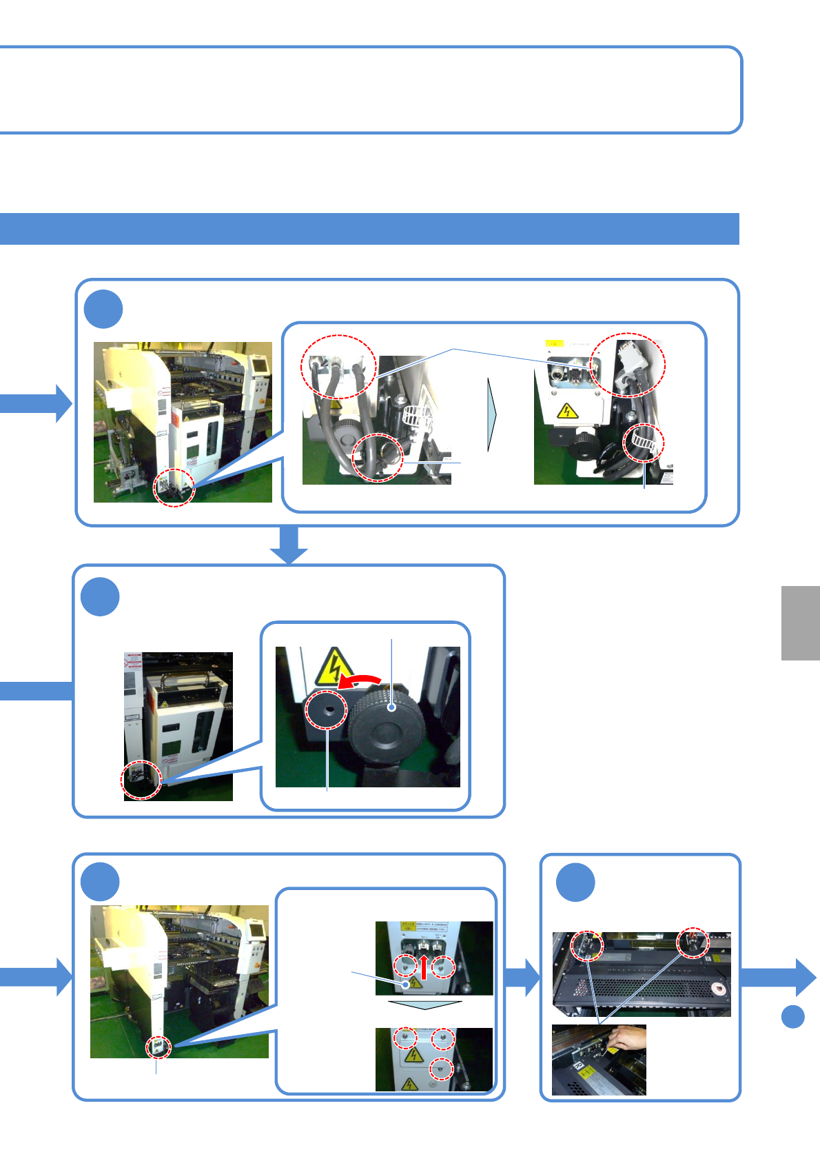
5
Remove the joint screw A and install it to the
temporary installation location
9
Attach the cover to the connector unit
10
●Screw: M4
2 locations
Detach the
feeder table
cover
Temporary installation location
Connector unit
To
11
4
Remove the cables and pipes and fix them using a cable tie
Cable tie
Clamping
band
Joint screw A
Cable, pipe
●Do not remove the clamping band
Cover
Installation
Fix the cover
●Screw:M4
Loosen
three screws
Loosen the screws and slide
the cover upward
●Screw:M4
Loosen
two screws