N7201A653E.pdf - 第451页
NPM- TT2 EJM1EE-MB-14 M-02 14-9 -6 To 19 18 B Push the end of the drive unit against the pin A, turn it clockwise so that its groove hits the pin B. Then tighten the screws. A ● Screw: M10 2 locations 15 Loosen t he scre…
NPM-TT2 EJM1EE-MB-14M-02
14-9-5
Maintenance
14-9
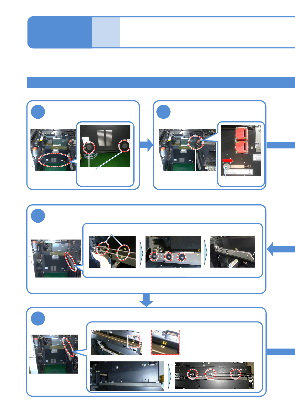
How to switch the 17-slot
feeder cart and the single
tray feeder 3
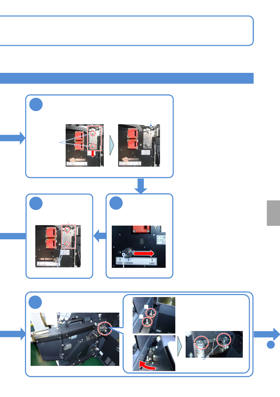
Attach the grommet
Loosen the knob, move it from
“TRAY” to “CHANGE” and fix
Tray feeder joint section
2 locations
Attach the drive guide
●Screw:M5 3 locations
Attach the cart guide
①Switching the single tray feeder to the 17-slot feeder cart 2
●Screw:M5 3 locations
1211
Sensor switch
Knob
16
17
Align the position of hinges and seals and tighten the screws
Installed state
Align the position of seals to position the cart guide
Tighten the screws to fix
NPM-TT2 EJM1EE-MB-14M-02
14-9-6
To
19
18
B
Push the end of the drive unit
against the pin A, turn it
clockwise so that its groove
hits the pin B. Then tighten
the screws.
A
●Screw: M10 2 locations
15
Loosen the
screws of the
sensor bracket
14
Loosen the knob,
move it from
“CHANGE” to
“CART” and fix
Knob
Installation
13
Loosen the screws all the way
Install the cart drive unit
Loosen the screws, pull the knob toward you,
move the sensor bracket downward and
temporarily fix the screws
Sensor bracket
Sensor switch
●Screw:
M4 2 locations
●Screw: M4 2 locations
Sensor bracket
knob
NPM-TT2 EJM1EE-MB-14M-02
14-9-7
Maintenance
14-9
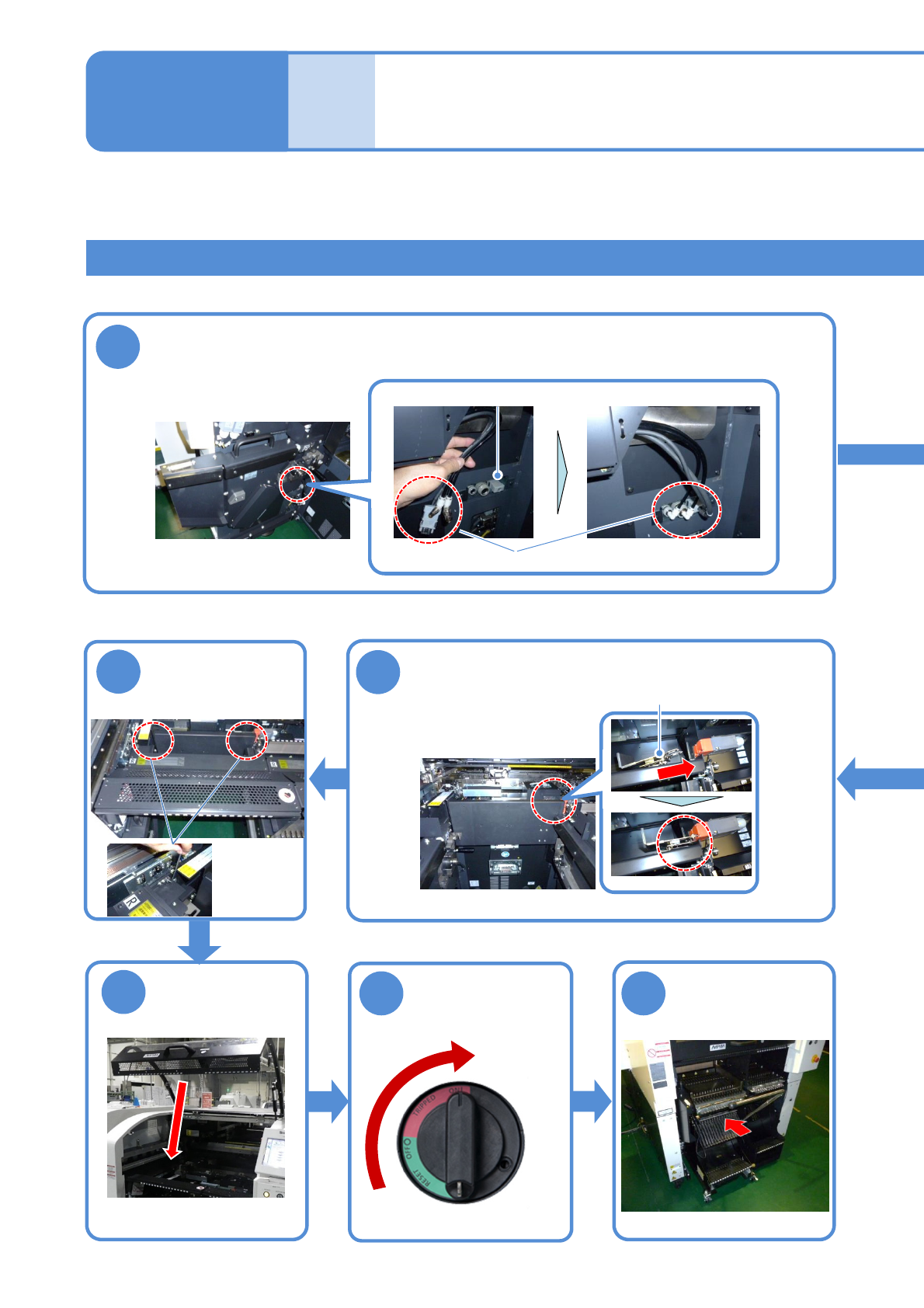
How to switch the 17-slot
feeder cart and the single
tray feeder 4
①Switching the single tray feeder to the 17-slot feeder cart 3
22
Insert the metal fitting of the safety cover to
the safety switch
23
Attach the
feeder table
cover
●Screw: M4
2 locations
19
Remove the short connector and install the cables and pipes of the cart
drive unit
Short connector
Store the removed short connector to the switch cart (→P.14-9-1)
24
25
ON
Unlock the
machine and
Metal fitting
Attach the feeder
cart
(→P.3-2)
26
Cable, pipe