N7201A653E.pdf - 第455页
NPM- TT2 EJM1EE-MB-14 M-02 14-9 -10 4 To 11 Push it until it goes inward from the multi-recognition camera Push the X-axis inward Remove the metal fitting of the safety cover from the safety switch 6 10 7 Loosen the scre…
NPM-TT2 EJM1EE-MB-14M-02
14-9-9
Maintenance
14-9
How to switch the 17-slot
feeder cart and the single
tray feeder 5
②Switching the 17-slot feeder cart to the single tray feeder 1
This explains how to switch between the 17-slot feeder cart and single tray feeder.
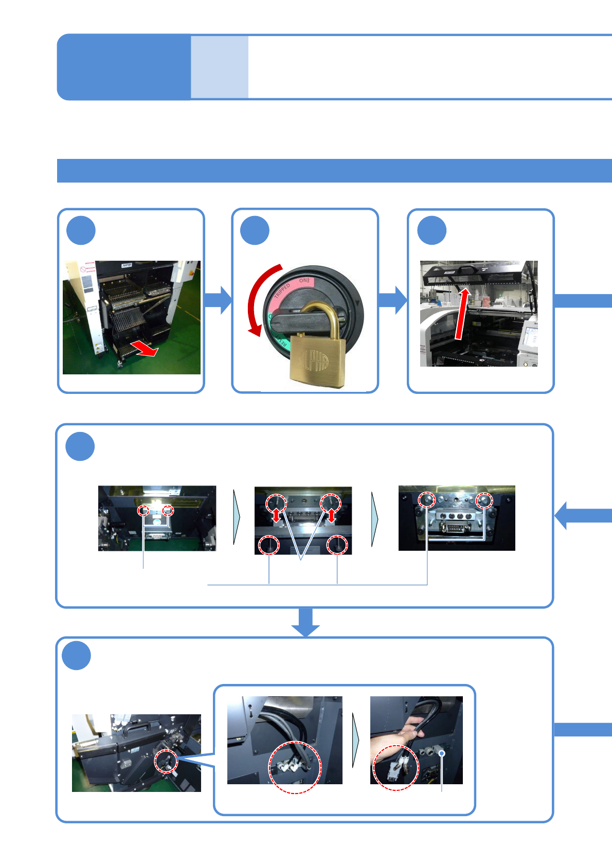
1
Turn OFF the
power and lock
the machine
Time required: 30 minutes
Tool used: Spanner 30 mm (2), Allen wrench (3 mm, 4 mm, 5 mm, 8 mm)
9
2
3
OFF
Detach the feeder
cart
Remove the extension drawer
Remove the cable and pipe of the cart drive unit and install the short
connector
(→P.3-2)
Loosen the screws
Short connector
8
●Screw: M6
2 locations
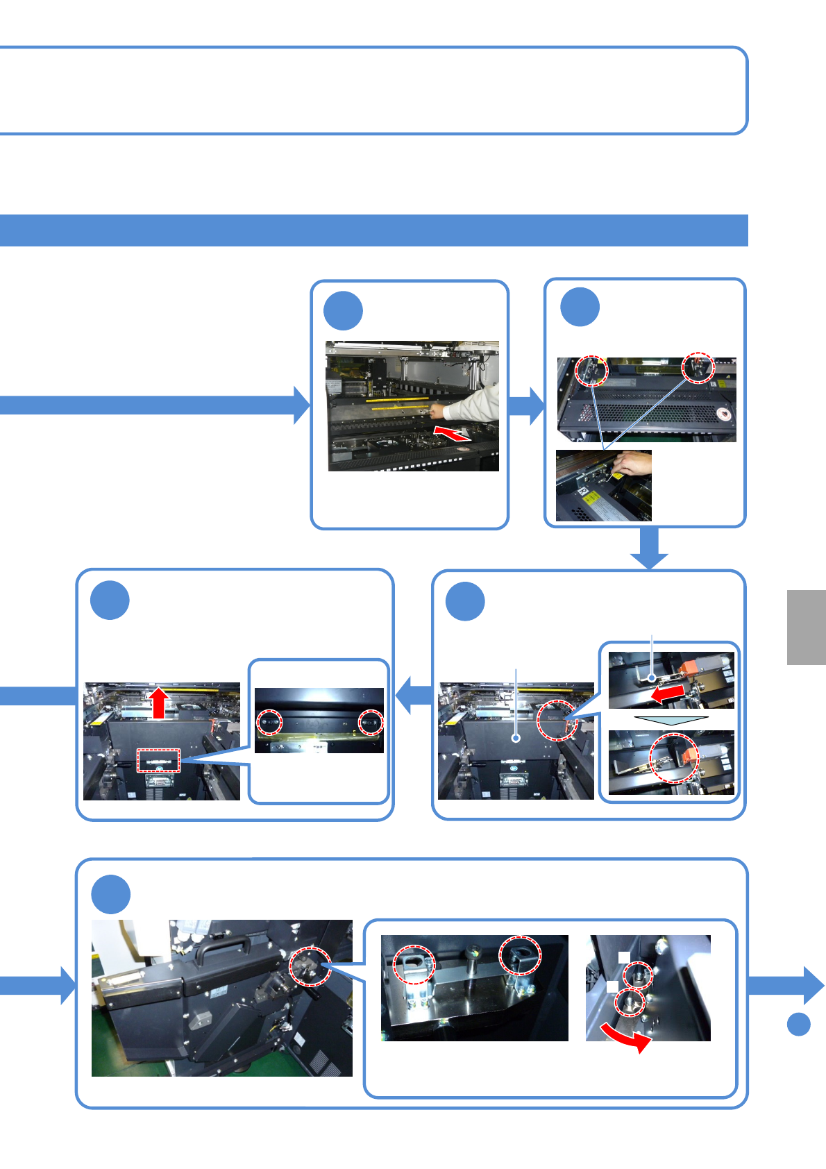
Store the removed extension drawer to the switch cart (→P.14-9-1)
Remove the extension drawer
Removed state
Pin
Put and tighten the screws
NPM-TT2 EJM1EE-MB-14M-02
14-9-10
4
To
11
Push it until it goes inward
from the multi-recognition
camera
Push the X-axis
inward
Remove the metal fitting of the
safety cover from the safety
switch
6
10
7
Loosen the screws of the
safety cover and pull the cover
upward to remove
●Screw: M6
2 locations
Loosen the screws of the cart drive unit and remove the unit
B
Turn the unit counterclockwise
to remove from the pin B and
pull it toward you
A
●Screw: M10
2 locations
5
●Screw: M4
2 locations
Detach the
feeder table
cover
Store the removed safety cover to the switch
cart (→P.14-9-1)
Metal fitting
Store the removed cart drive unit to the switch cart (→P.14-9-1)
Safety cover
Installation
NPM-TT2 EJM1EE-MB-14M-02
14-9-11
Maintenance
14-9
How to switch the 17-slot
feeder cart and the single
tray feeder 6
②Switching the 17-slot feeder cart to the single tray feeder 2
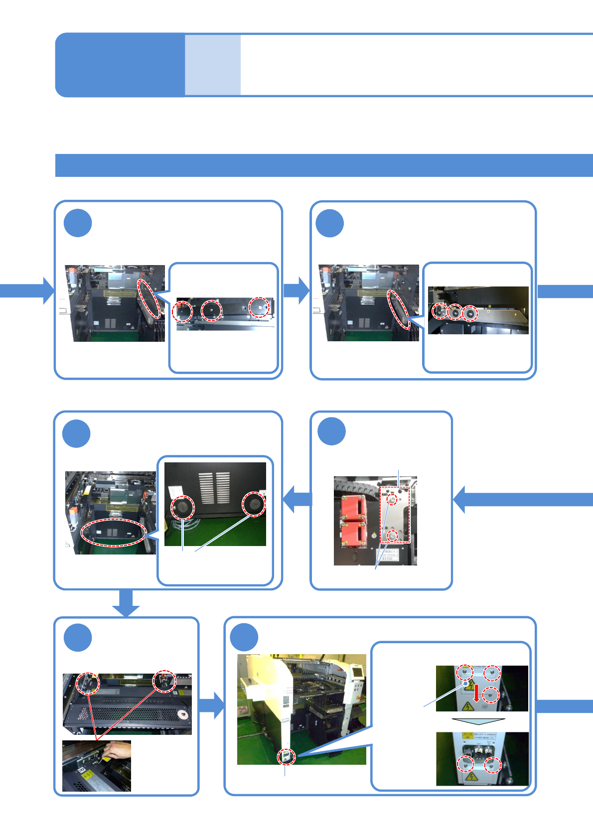
11
12
Detach the drive guide
Detach the cart guide
18
●Screw: M4
2 locations
Attach the feeder
table cover
19
Connector unit
Store the removed drive guide to the switch cart
(→P.14-9-1)
●Screw: M5
3 locations
Store the removed grommet to
the switch cart
(→P.14-9-1)
16
Loosen the
screws of the
sensor bracket
Loosen the screws and slide the
cover lower
●Screw: M4
Loosen
3 screws
Fix the cover
●Screw: M4
Loosen
2 screws
Cover
Remove the cover of the connector unit
Store the removed cart guide to the switch cart
(→P.14-9-1)
●Screw: M5
3 locations
Detach the grommet
Tray feeder joint section
2 locations
17
●Screw: M4 2 locations
Sensor bracket