N7201A653E.pdf - 第493页
NPM- TT2 EJM1 EE-MB-17M-00 Detach the tray feeder Switch the sensor ① Detach the tray feeder ② Remove the c over and ins tall in s uch a wa y that the c onnectors are covered (3 mm Allen wrench) Loosen the knob and fix i…
NPM-TT2 EJM1EE-MB-17M-00
Switch from the single
tray feeder to the 17-slot
feeder cart 1
Maintenance
17-4
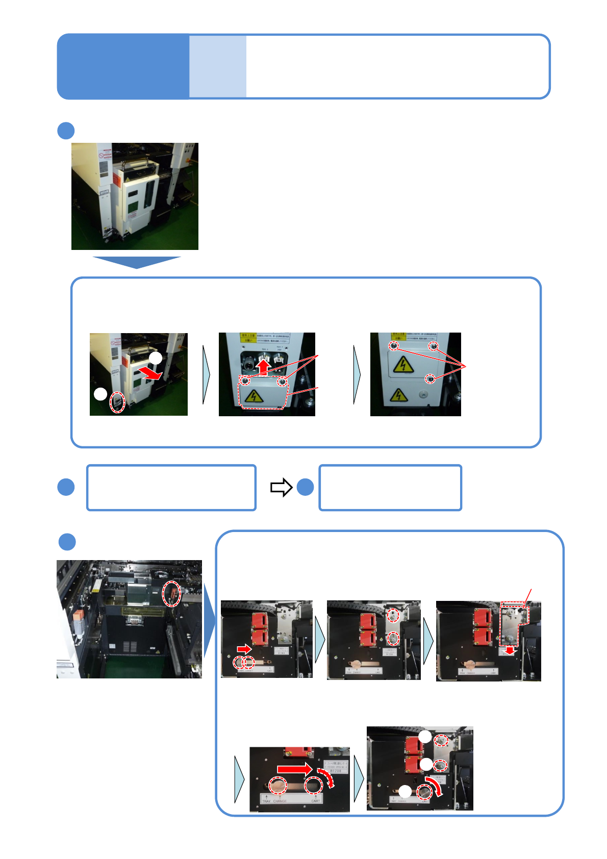
Remove the cables and screw
Release the safety switch
Turn OFF the power
(→ P.17-2-1)
Pull out the metal
part
Remove the
connection screw
① Rotate the metal part in a
counterclockwise
②Attach the connection
screw under it
Attach the connection
screw on the left side
Remove the three
connectors
Bundle the three
cables
Open the cover and push the
X-axis inward (→P.17-2-2)
①
②
17-4-1
2
1
3
4
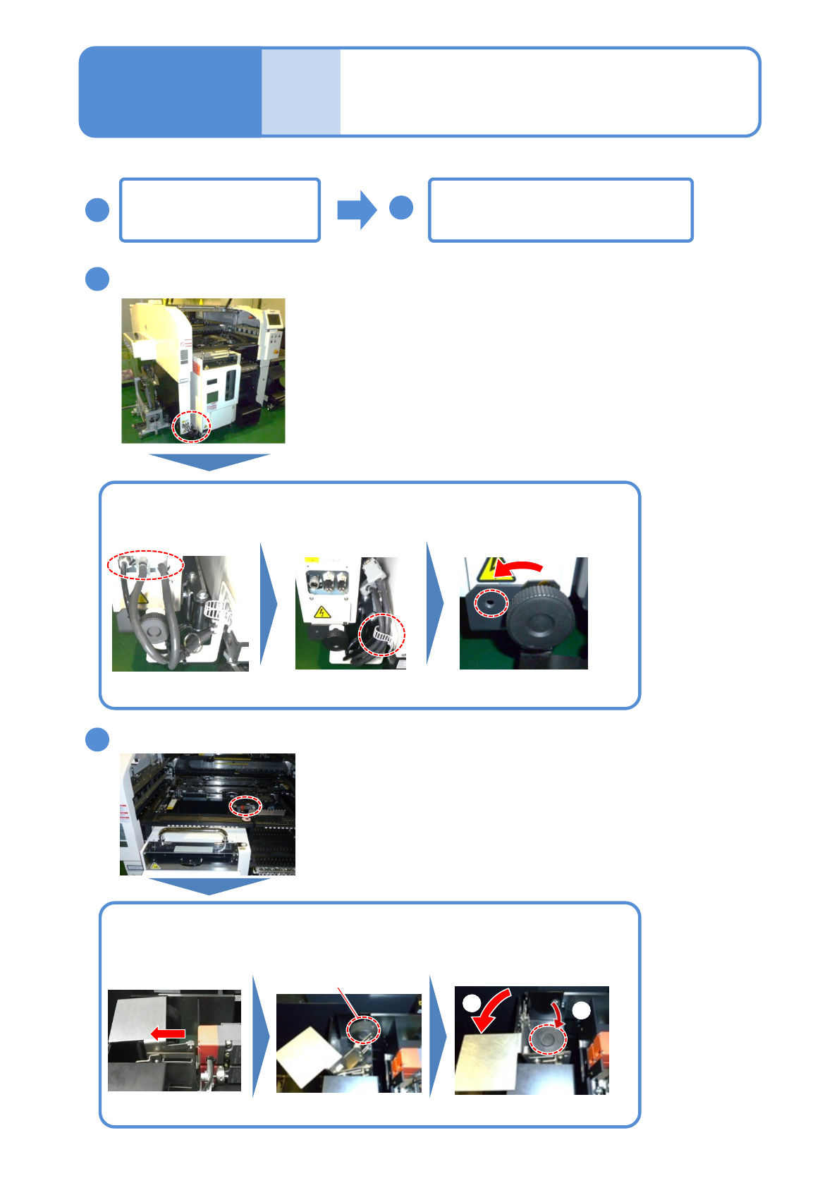
Describes the procedure for switching from the tray feeder to the 17-slot feeder cart.
NPM-TT2 EJM1EE-MB-17M-00
Detach the tray feeder
Switch the sensor
①Detach the tray feeder ②Remove the cover and install in such a way that the connectors are
covered (3 mm Allen wrench)
Loosen the knob and
fix it at the CHANGE
position
Loosen screws all the
way (3 mm Allen
wrench)
Hold the bracket knob
and lower it approx. 10
mm
①
②
Detach the feeder table
cover(→ P.17-2-3)
Loosen the knob and
temporarily fix it at the
CART position
①Tighten the
screws (3 mm
Allen wrench)
①
②
②Finally
tighten the
knob
①
Attach the grommet
(→P.17-2-4)
●2 locations
●2 locations
17-4-2
5
6 7
Screw
(2)
Cover
Screw(3)
8
Knob
Switch from the single
tray feeder to the 17-slot
feeder cart 2
Maintenance
17-4
NPM-TT2 EJM1EE-MB-17M-00
Switch from the single
tray feeder to the 17-slot
feeder cart 3
Maintenance
17-4
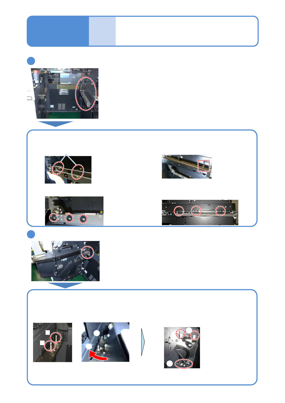
Install the guides (two types)
Install the cart drive unit
B
A
①
②
①Place the edge of the drive unit on the Pin A
②Rotate the drive unit in a clockwise direction
to fit into the pin B
Use (a) Cart drive unit of the feeder cart (→P.17-3-1)
Use (b) Drive guide and (c) Cart guide of the switch cart (→P.17-3-1)
Store the removed (f) Short connector in the
part box of the switch cart (→P.17-3-1)
17-4-3
9
10
③Tighten the screws (8 mm Allen wrench)
●2 locations
④Remove the shot connector on the right
side and connect the connector in
accordance with its shape
(c)Cart guide
(b)Drive guide
①Align the pin and seal positions
② Tighten the screws to secure
(4mm Allen wrench)
●3 locations
①Align the seal position
②Tighten the screws to secure
(4mm Allen wrench)
●3 locations
④
③