N7201A653E.pdf - 第73页
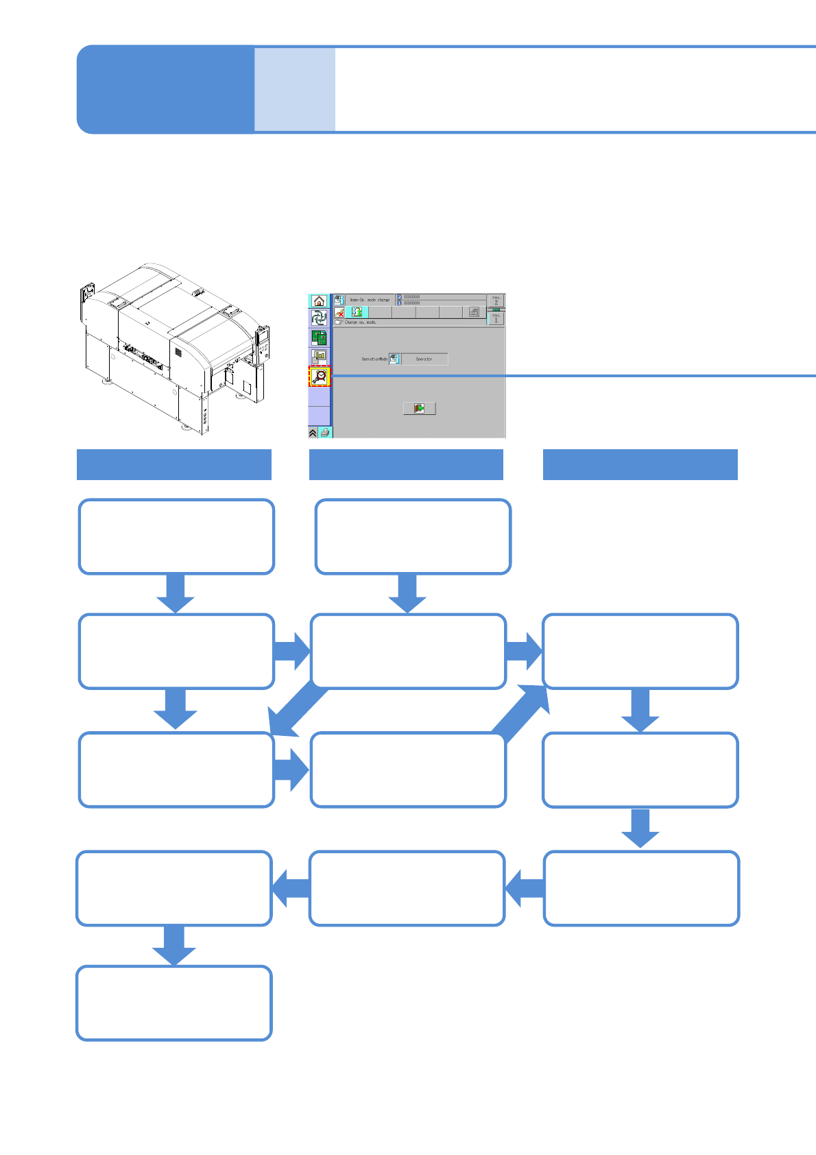
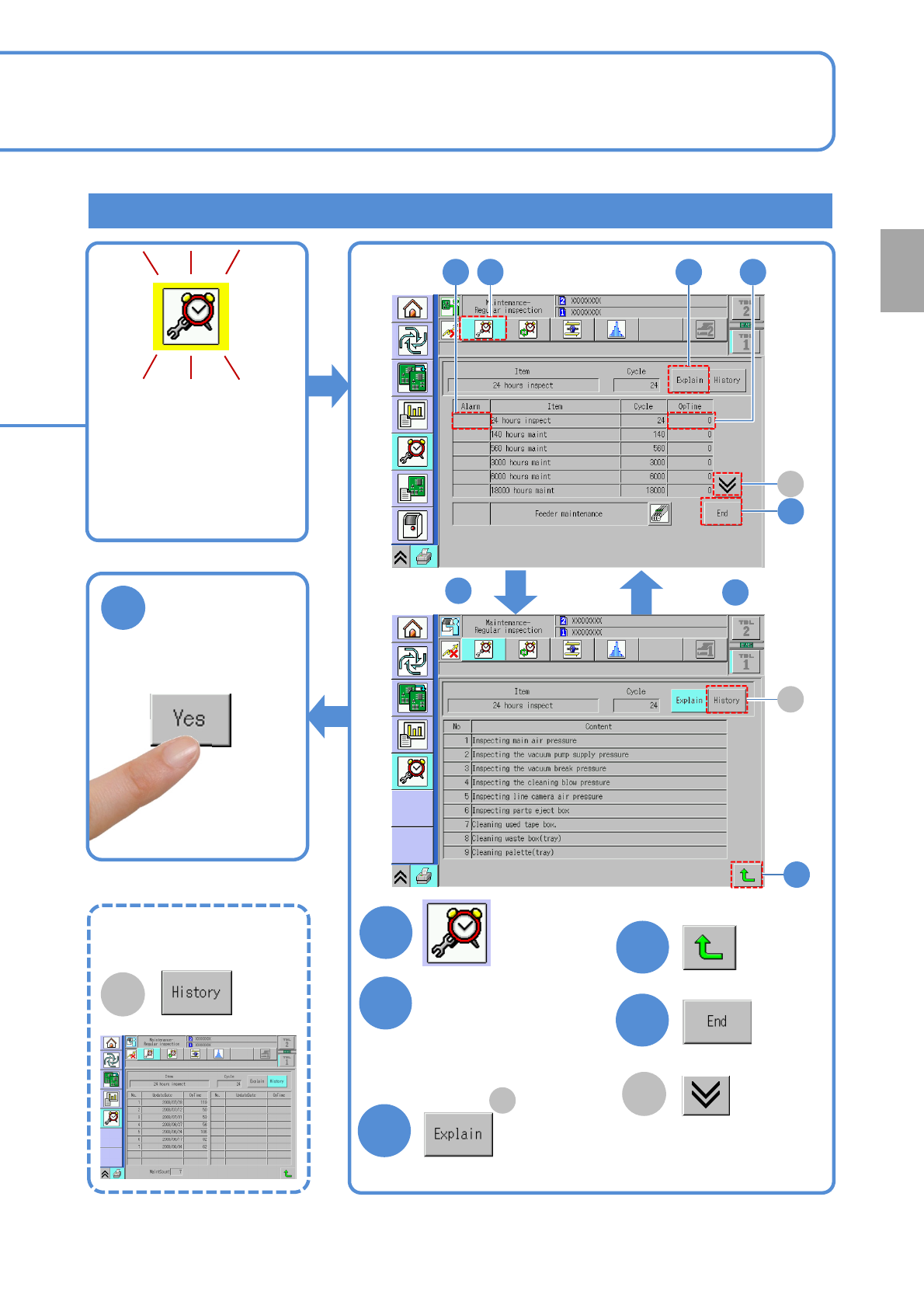
NPM- TT2 EJM1EE-MB-02M-0 1 Confirming a cycle and details of work, history information When 80% of the maintenance cycle is reached, a flashing yellow-colored message is displayed on the [Maintenance menu] screen. 2-1-1 …
NPM-TT2 EJM1EE-MB-02M-01
Overview
Maintenance overview
Equipment
Screen (Alarm)
Work
2-1-1-1
Maintenance
2-1-1
Operating time is
accumulated
Operating time since
the last maintenance is
accumulated
Normal display
80% of the
maintenance
cycle has elapsed…
A flashing yellow
colored message is
displayed
Confirmation of task
details
A flashing red colored
message is displayed
Full maintenance cycle
has elapsed and
maintenance is due
Update historyNormal display
The next maintenance
timing is automatically
calculated
Perform maintenance
●This equipment notifies you of the time for periodic maintenance, automatically calculating it from operating
time.
●When you notify the machine that a particular maintenance task is complete, the task completion is saved in
the history. (This information serves as the new reference to calculate the next maintenance timing.)
NPM-TT2 EJM1EE-MB-02M-01
Confirming a cycle and details of work, history information
When 80% of the
maintenance cycle is
reached, a flashing
yellow-colored message
is displayed on the
[Maintenance menu]
screen.
2-1-1-2
6
Confirm the message
Overview
1
4
3
4
5
2
Choose an item that
warning is shown in
the Alarm field.
(Press the ‘OpTime’)
Confirm task details
After maintenance
After
After
3
4
3
5
2 1 2
A
B
A
●Change to another
screen
A
Change to the limited-life
components screen
■To view
maintenance history
B
NPM-TT2 EJM1EE-MB-02M-01
Overview
Periodic inspection
items by cycle 1
Every-24-hours (daily) inspection items
Every-140-hours (weekly) inspection items
2-1-2-1
Maintenance
2-1-2
The lists below show check and grease locations/information organized by cycle.
Indications in the Power field mean as follows: “ON” = inspect with Power ON, “OFF” = inspect with Power
OFF, and “-” = inspect with Power ON or OFF.
■ Types in common
No. Unit Check and greasing location Power
Check and
greasing points
Time
[min]
Ref.
1 Main body
Main air pressure
(Pressure gauge)
ON
Air pressure check
(Before operation)
3 4-1-1
Vacuum pump supply pressure
(Pressure gauge)
Vacuum break pressure
(Pressure gauge)
Cleaning blow pressure
(Pressure gauge)
Components-ejection box -
Cleaning
(End of operation)
3 4-2-1
2 13-slot feeder Inside of the used-tape box -
Cleaning
(End of operation)
1 4-2-2
■ Others (Option)
No. Unit Check and greasing location Power
Check and
greasing points
Time
[min]
Ref.
1 Tray feeder Refuse box -
Cleaning
(End of operation)
1 4-2-3
2
Tray feeder pallet
(per pallet)
Pallet
Cleaning, check
(End of operation)
2 4-3-1
3 Feeder cart Inside of the used-tape box -
Cleaning
(End of operation)
1 4-2-2
■ Types in common
No. Unit Check and greasing location Power
Check and
greasing points
Time
[min]
Ref.
1 Touchscreen Touchscreen face OFF Cleaning 3 5-1
2 PCB conveyor PCB-support blocks OFF Cleaning 10 5-3
3
Multi-recognition
camera
Cover glass OFF Cleaning 5 5-4
4 13-slot feeder
Feeder table
-
Cleaning 15 5-5
Connector Check 15 5-3
5
PCB support block
(standard)
PCB support block OFF Cleaning 10 5-3
Inspection time (min) = 6 + 1 x (the number of 13-slot feeder)
Inspection time (min) = 1 x (the number of tray feeders) + 2 x (the number of pallets)
1x(the number of feeder carts)
Inspection time (min) = 28 + 30 x (the number of 13-slot feeder)