N7201A653E.pdf - 第83页
NPM- TT2 EJM1EE-MB-02 M-01 2-1-3 -4 ■ Others No. Unit name Check and greasing location Check and grease points Cycle [h] Ref. 24 140 560 1000 3000 6000 18000 1 Components- ejection conveyor (option) Component detection s…
NPM-TT2 EJM1EE-MB-02M-01
2-1-3-3
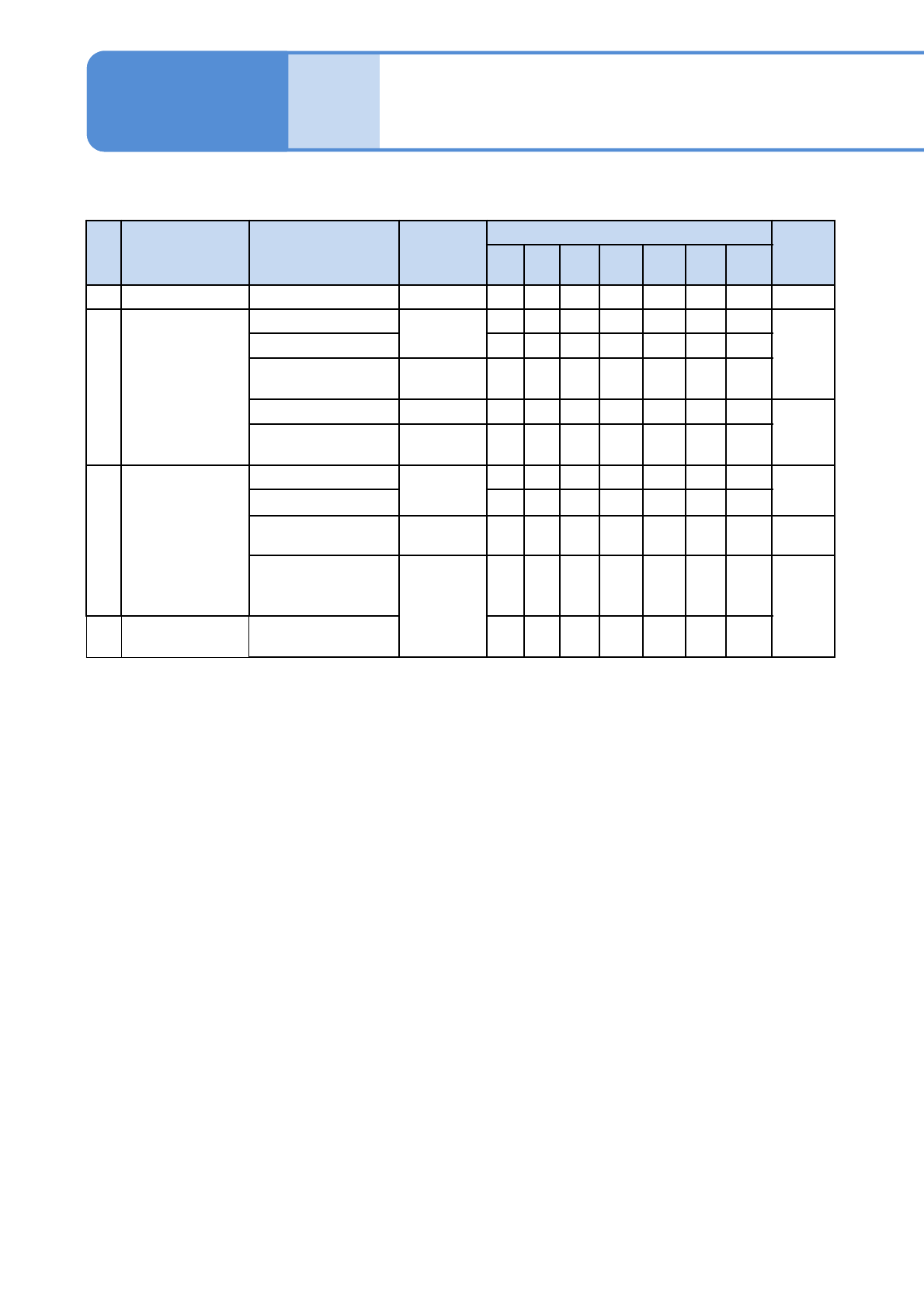
■ 3-nozzle head (option)
No. Unit name
Check and
greasing location
Check and
grease
points
Cycle [h]
Ref.
24 140 560 1000 3000
600
0
1800
0
1 Placement head Large reflector Cleaning
○
6-6
2 Nozzle holder
Filter
Cleaning
○
5-2
Taper surface
○
Clamp claw
Grease
dispensing
○
Clamp claw Check
○
10-1
Spring for holding
clamp claws
Check
○
3 Nozzle
Nozzle reflector
Cleaning
○
6-4
Nozzle tip
○
1006 nozzle Check
○
9-3
Nozzle flange
surface
(2D code area)
Cleaning
○
6-4
4 Nozzle changer
Nozzle reflector
contact surface
○
Overview
Periodic inspection
items by unit 2
Maintenance
2-1-3
NPM-TT2 EJM1EE-MB-02M-01
2-1-3-4
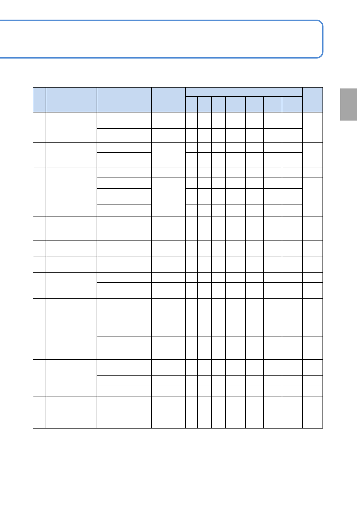
■ Others
No. Unit name
Check and
greasing location
Check and
grease
points
Cycle [h]
Ref.
24 140 560 1000 3000 6000 18000
1
Components-
ejection
conveyor
(option)
Component
detection sensor
Cleaning
○
6-12
Conveyor belt Cleaning
○
2
Tray feeder lifter
(option)
Ball screw
Apply
grease
○
6-13
Linear guide
○
3
Tray feeder
drawer
(option)
Table surface Cleaning
○
5-6
Linear guide
Grease
dispensing
○
6-13
Cam plate
(Inside)
○
Cam block
○
4
Tray feeder
magazine
(option)
Slot Cleaning
○
6-14
5
Tray feeder
(option)
Refuse box Cleaning
○
4-2-3
6
Tray feeder
pallet (option)
Pallet
Cleaning,
Check
○
4-3-1
7
Extension
conveyor
(option)
PCB transfer belt Check
○
6-5
PCB detection
sensor
Cleaning
○
6-9
8
Support pin
automatic
change (option)
PCB support
block (for
automatic change),
Support pin (for
automatic change)
Cleaning
○
5-3
Nozzle / nozzle
changer for
support pins
Cleaning
○
6-18
9
Feeder cart
(option)
Inside of the used-
tape box
Cleaning
○
4-2-2
Feeder table Cleaning
○
5-5
Connector Check
○
5-7
10
Height sensor
(option)
Incoming and
receiving parts
Cleaning
○
6-19
11 LNB(option)
Filter
(FA computer)
Cleaning
○
8-2
Overview
NPM-TT2 EJM1EE-MB-02M-01
Overview
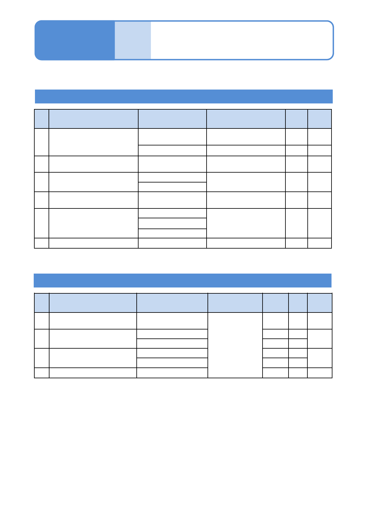
Periodic inspection items
by applying grease
2-1-4
Maintenance
2-1-4
No.
Unit Location Grease
Cycle
[h]
Ref.
1
Nozzle holders
(8-nozzles)
Nozzle holder slicing
surface
FL100
140 7-1
Clamp claw BARRIERTA IEL/V 560 6-3
2
Transfer head
(3-nozzle)
Clamp claw BARRIERTA IEL/V 140 5-2
3 PCB conveyor
Linear guide
LCG100 560 6-1
Ball spline
4
Nozzle holders
(8-nozzles)
Spring for holding
clamp claw
BARRIERTA IEL/V 560 6-3
5
Tray feeder drawer
(Option)
Linear guide
LCG100 560 6-13
Cam plate (inside)
Cam block
6 Touchscreen Hinge TOUCH LUBE 6000 9-2
No.
Unit Location Grease
Amount
[cm
3
]
Cycle
[h]
Ref.
1 PCB conveyor
Width-adjustment ball
screw
LCG100
3.6 560 6-1
2 XY unit
X-axis linear guide 2 560
6-2
Y-axis linear guide 4 560
3
Tray feeder lifter
(Option)
Ball screw 1.8 560
6-13
Linear guide 7.2 560
4 13-slot feeder Cutting unit 1.8 560 6-17
Grease dispensing
The lists below show grease locations and names organized by the target unit.
Apply grease