MAN00000772_SI-G200BB_SVCPDFA.pdf - 第114页
Install Tray Unit (Re-setup after tray unit moved) SEET 2/19 WKGB-10105-02 Installing Tray Unit (Re-setup after tray unit moved) [Connection with main body] 1 Connect the tray coupling I/F plate and S axis, V axis unit s…
Install Tray Unit (Re-setup after tray unit moved)
SEET
1/19
WKGB-10105-02
Installing Tray Unit
(Re-setup after tray unit moved)
Install Tray Unit (Re-setup after tray unit moved)
[Necessary jig/tool]
・Spanner(17[mm],24[mm],30[mm])
・Hex-Wrench(10 [mm] )
・Scale(300[mm])
・Thickness Gauge(0.03[mm], 0.1[mm], 0.5[mm], 1.0[mm])
Install Tray Unit (Re-setup after tray unit moved)
SEET
2/19
WKGB-10105-02
Installing Tray Unit
(Re-setup after tray unit moved)
[Connection with main body]
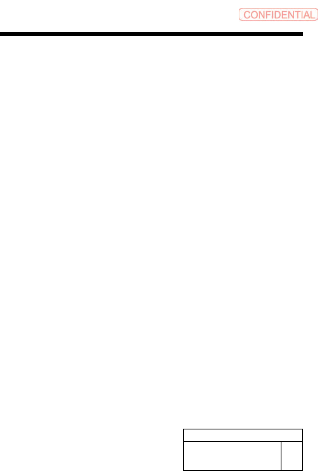
1 Connect the tray coupling I/F plate and S
axis, V axis units.
1. Connect the AIR tube on the tray I/F plate to the
manifold on the lower section of the S axis with air
tube ofφ6.
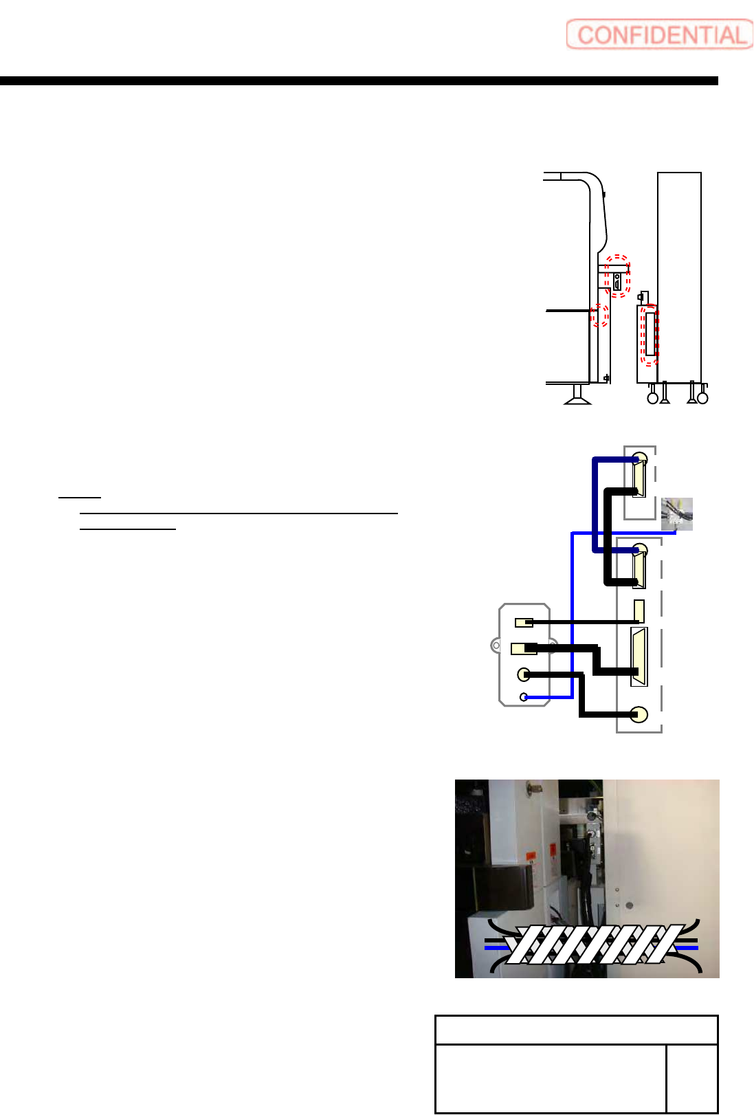
2. Connect each connector on the tray I/F plate to
each connector on the V axis unit.
TY-MLOUT <======> CU-1
TY-CTLOUT <======> TY-CTL
TY-ACOUT <======> TY-ACIN
3. Connect the S axis unit and the V axis unit.
S-SMT1 <======> S-SMT2
VD-IO <======> S-IO
NOTE:
At this time, do not dock the tray unit and the
main body yet.
2 Bind the cable with spiral tube after
connection.
TY-MLOUT
T
Y
-CTLOUT
T
Y
-ACOUT
AIR
CU1
TY-CTL
TY-ACIN
VD-SMT
VD-IO
S-SMT2
S-IO
Install Tray Unit (Re-setup after tray unit moved)
SEET
3/19
WKGB-10105-02
Installing Tray Unit
(Re-setup after tray unit moved)
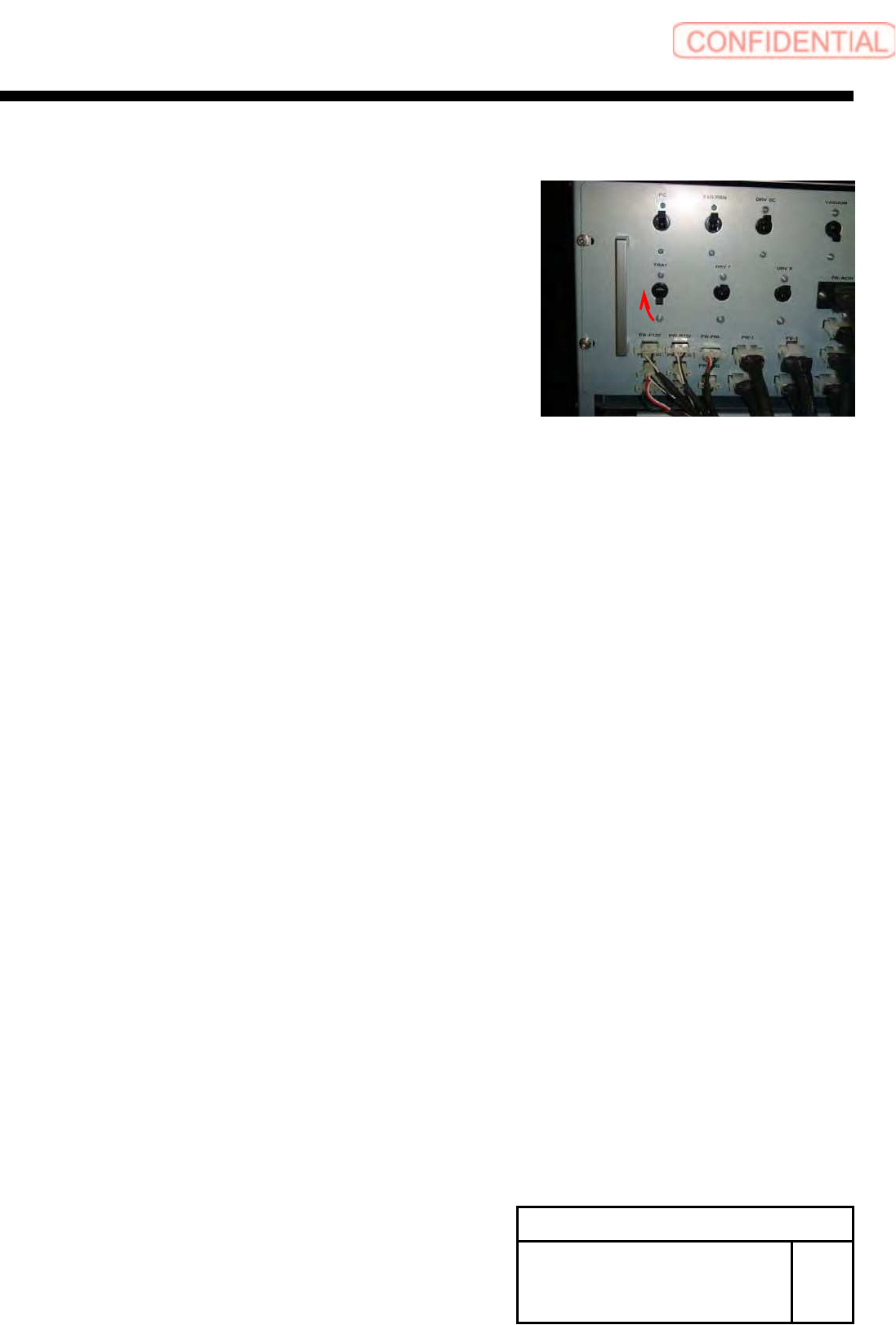
3 Turn ON the TRAY breaker for the rear
power unit.