MAN00000772_SI-G200BB_SVCPDFA.pdf - 第149页
O pe r a ti on Guide W o rk Pr ocess Parts R e placem ent Maintenan ce I ntended i tem S I -G200 A A BB Docume n t no. W KGB - 20105-0 1 Page 7/8 4. T aking o ff S H terminals of upper f r ame Loos en 2 P4 x 6 t o take o…
Operation Guide Work Process Parts Replacement Maintenance
Intended item SI-G200 AA BB
Document no. WKGB-20105-01
Page 6/8
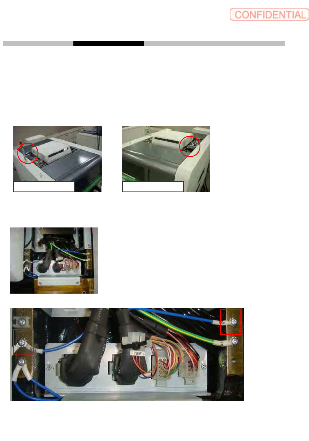
Enlarged (Completed 2 spots, left side)
Enlarged (Completed 2 spots, right side)
Operation Guide Work Process Parts Replacement Maintenance
Intended item SI-G200 AA BB
Document no. WKGB-20105-01
Page 7/8
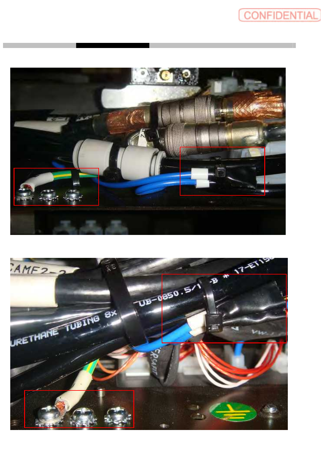
4. Taking off SH terminals of upper frame
Loosen 2 P4 x 6 to take off SH terminal from XFM1 (XRM1), XFM2 (XRM2). After taking off SH
terminals fix 2 P4 x 6 and tooth lock washers.
Wrap SH Terminal with plastic tape to fix nylon tie
This process should be done for front and rear side.
Y Cable rear side Y Cable front side
Work spot
Enlarged
(2 spots)
Machine front left Machine front right
Operation Guide Work Process Parts Replacement Maintenance
Intended item SI-G200 AA BB
Document no. WKGB-20105-01
Page 8/8
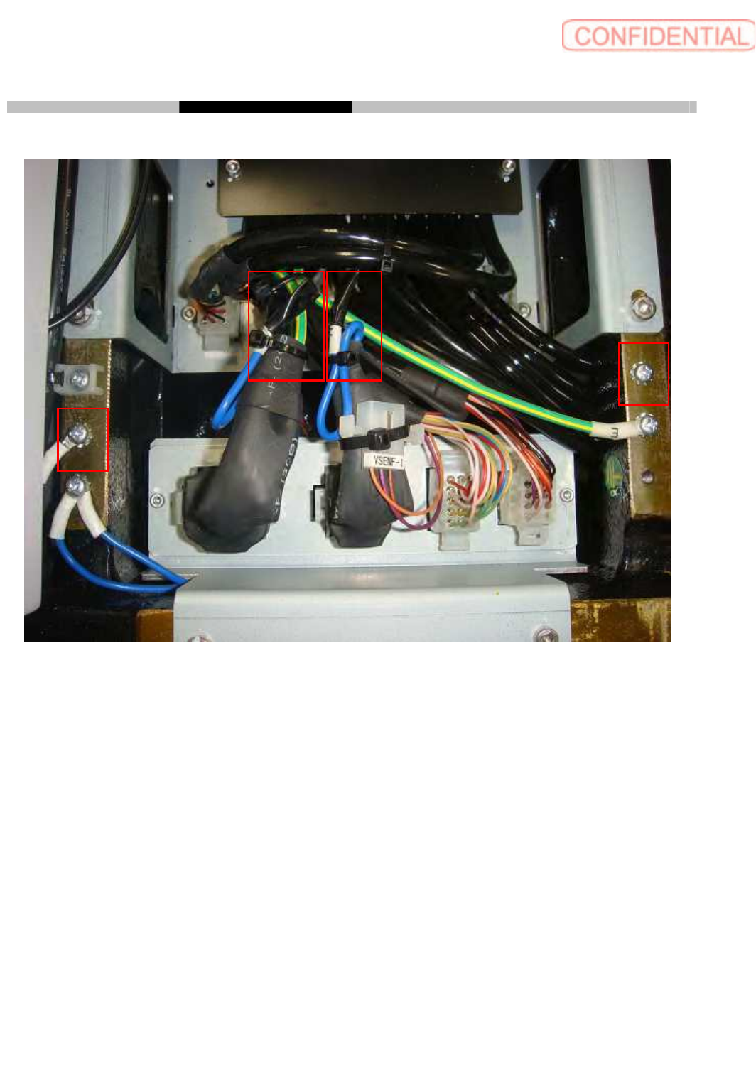
Enlarged (Completed)
5. Return back original condition
Put back side sealing parts to fix with CP 4 x 8.
Put back tower light position to fix with 4 CP 4 x 15.
Put back top plates to fix with CP 4 x 45.
Put back connector covers to fix with 8 CP 3 x 6.