MAN00000772_SI-G200BB_SVCPDFA.pdf - 第164页
Preparation for Calibration HLGB-10105-01 Calibration Dat a Load SHEET 2/3 3 Click in an order of M/C SETUP menu M/C MAINTENANCE tab Calibration tool selection button. A sele ct screen for jig used for calibration ap…
Preparation for Calibration
HLGB-10105-01
Calibration Data Load
SHEET
1/3
Calibration Data Load
[Necessary jigs]
• Calibration data FD
[Procedure]
1 Record the description in the existing calib.ini.
< When performing calibration for the front head >
Record a value of MOUNT_HEIGHT,FIXED_INSP_HEIGHT in “c:¥asm¥mcdata1¥head.ini”.
< When performing calibration for the front head >
Record a value of MOUNT_HEIGHT,FIXED_INSP_HEIGHT in the “c:¥asm¥mcdata2¥head.ini”.
If there’s no description in Calib.ini, refer to the following.
Same value as MOUNT_HEIGHT in NOZZLE_S_TYPE_G = head.ini
A value obtained by subtracting “3” from MOUNT_HEIGHT in NOZZLE_T_TYPE_G = head.ini
A value of H of [FixedCamera] POS_XYH in FIXED_INSP_HEIGHT = head.ini
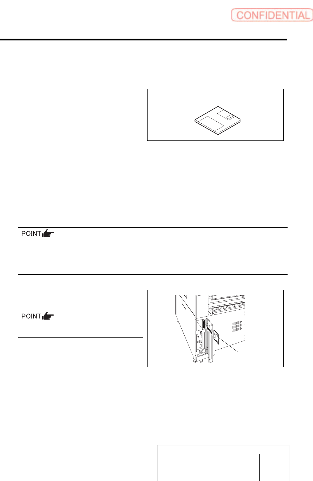
2 Set a FD including calibration plate
data(calib.ini) into the FD drive of the unit.
Use a FD having a same No as the ball point
jig.
Calibration data FD
Calibration data FD
Preparation for Calibration
HLGB-10105-01
Calibration Data Load
SHEET
2/3
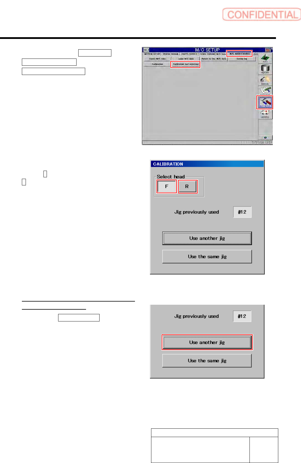
3 Click in an order of M/C SETUP menu
M/C MAINTENANCE tab
Calibration tool selection button.
A select screen for jig used for calibration appears.
4 Select head to be calibrated.
Press the F button for the front head, and press the
R for the rear head.
5 Select jig used for calibration.
<When the indicated jig No is different
form jig No to be used>
1. Press the Use another jig button.
Calibration plate data is read into the unit, and jig
select screen is closes.
Preparation for Calibration
HLGB-10105-01
Calibration Data Load
SHEET
3/3
After loading jig data, check the following description in Calib.ini.
・ Should be same value as MOUNT_HEIGHT in NOZZLE_S_TYPE_G = head.ini.
・ Should be a value obtained by subtracting “3” from MOUNT_HEIGHT in NOZZLE_T_TYPE_G =
head.ini .
・ Should be a value of H of [FixedCamera] POS_XYH in FIXED_INSP_HEIGHT = head.ini.
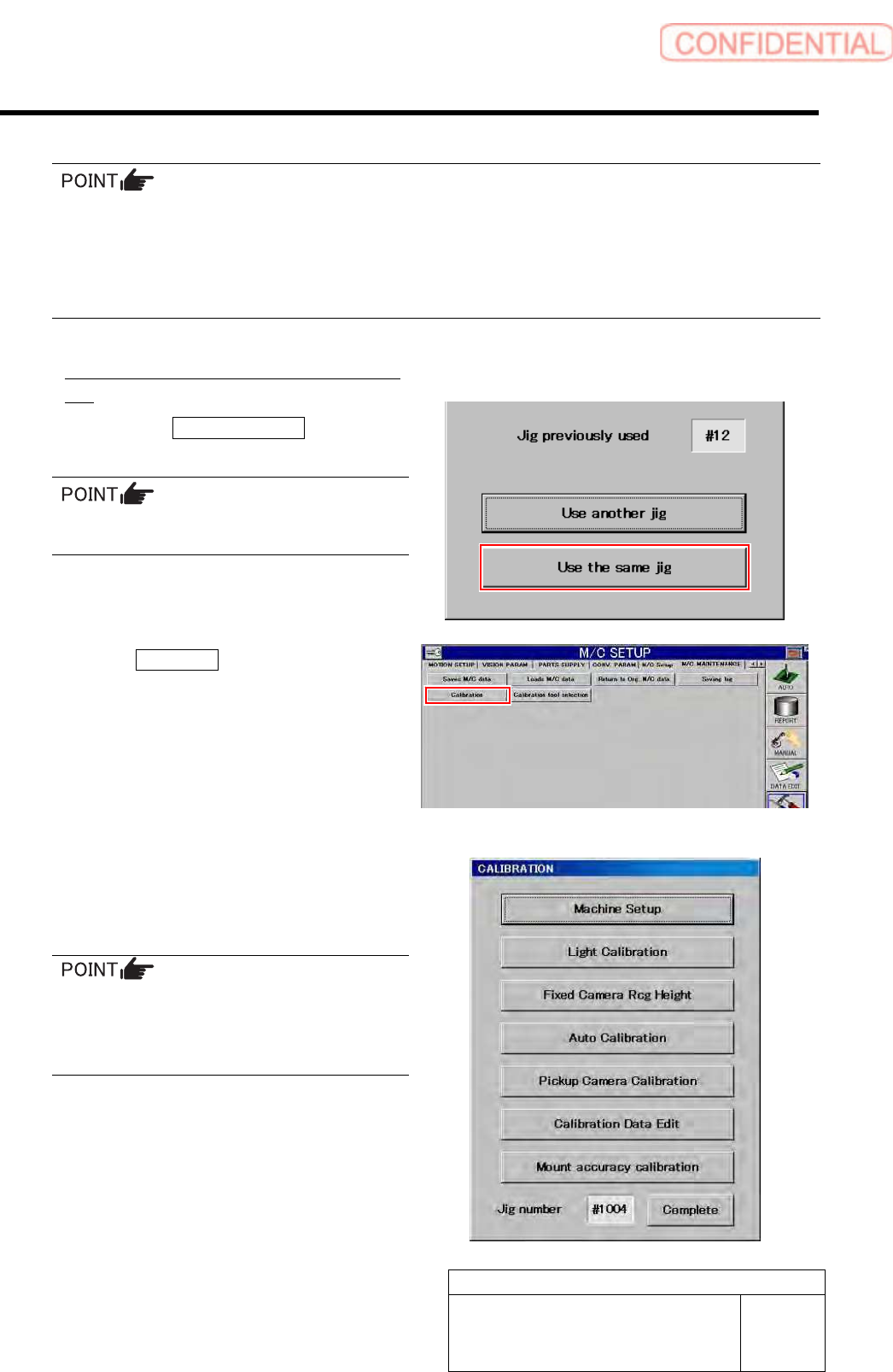
<When using same jig No as the indicated jig
No>
1. Press the Use the same jig button.
The Jig Select screen closes.
When performing calibration again, use the
previously used jig wherever possible.
6 Click the Calibration button.
“ Head at opposite position will be moved to
noninterference area. Press the [START] button if you
are really OK.” is displayed on the message screen.
7 Press the [START] button on the operation
panel.
CALIBRATION screen is displayed.
For machine setup and respective calibrations
described in the following pages, the respective
operation screens can be opened from this menu.
Perform calibration sequentially from the
upper on this menu screen.
Any buttons displayed in gray become effective
by completing calibration items on the above.