MAN00000772_SI-G200BB_SVCPDFA.pdf - 第167页
Preparation for Calibration HLGB-10106-01 Origin Return of the Unit (M/C ORG) SHEET 2/2 5 Press [ORG] button in front of the unit. When origin return is star ted, the green lam p on the signal tower blinks. < Operatin…
Preparation for Calibration
HLGB-10106-01
Origin Return of the Unit (M/C ORG)
SHEET
1/2
Origin Return of the Unit (M/C ORG)
[Procedure]
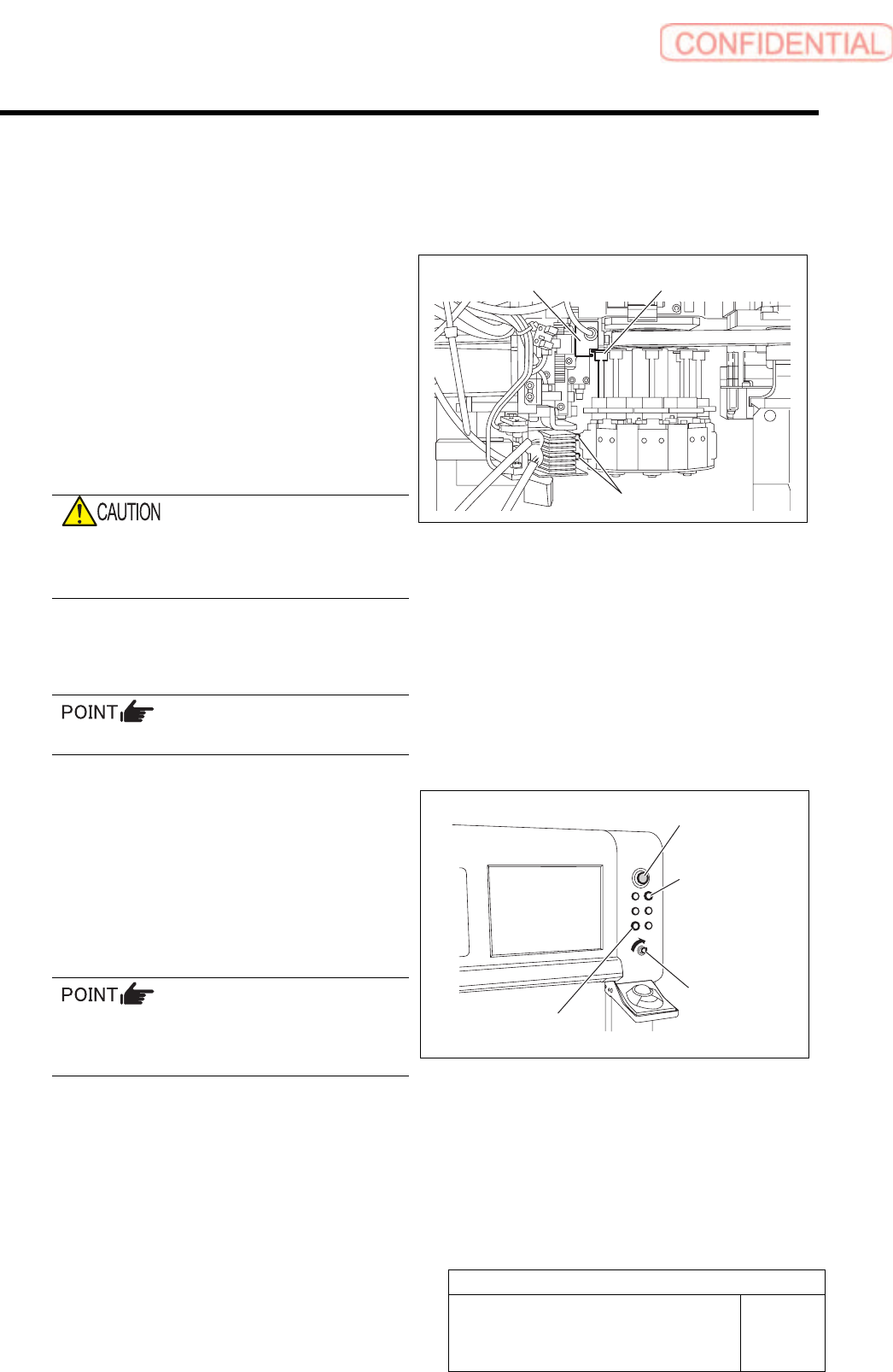
1 Check stop position of head part.
1. Check that two plungers are
withdrawn.
2. Turn RT axis to a position where inner
shaft upper end matches H axis
pusher.
When the position is deviated, turn the RT axis to
align positions of the inner shaft and H axis
pusher.
If origin return is performed while the RT axis
deviates from the plunger.
Be sure to match them to the above position.
2 Insert the front and rear alternation carts into
the unit.
It is unnecessary to raise the alternation carts.
3 To secure safety, close the front and rear
doors for the unit and turn ON the interlock
key.
4 Press the Operation priority button
(FRONT/REAR button).
For any malfunction of the unit during origin
return, prepare to immediately press the
emergency stop switch.
Inner shaft upper end
H axis pusher
Plunger
Emergency stop
switch
Operation priority
button
ORG button
Interlock key

Preparation for Calibration
HLGB-10106-01
Origin Return of the Unit (M/C ORG)
SHEET
2/2
5 Press [ORG] button in front of the unit.
When origin return is started, the green lamp on the
signal tower blinks.
< Operating sequence of origin return >
1. Origin return of H/F axis
For head on the front side, left front is origin
position, and for head on the rear side, right
depth is origin position.
2. Origin return of X/Y axis, RT/RN axis
Turn OFF the interlock key when removing the alternation cart after origin return or when opening the
door to perform working.
Since the function of the area sensor is enabled when the interlock key is ON, the unit is in the emergency
stop state if your hand etc is put into the unit.
Similarly, when the alternation cart is removed from the unit with the interlock being ON, the unit is in
the emergency stop.
Set-up
HLGB-10201-01
RT Axis Origin Position Setup
SHEET
1/4
RT Axis Origin Position Setup
Perform this working on both heads on the front side and rear side.
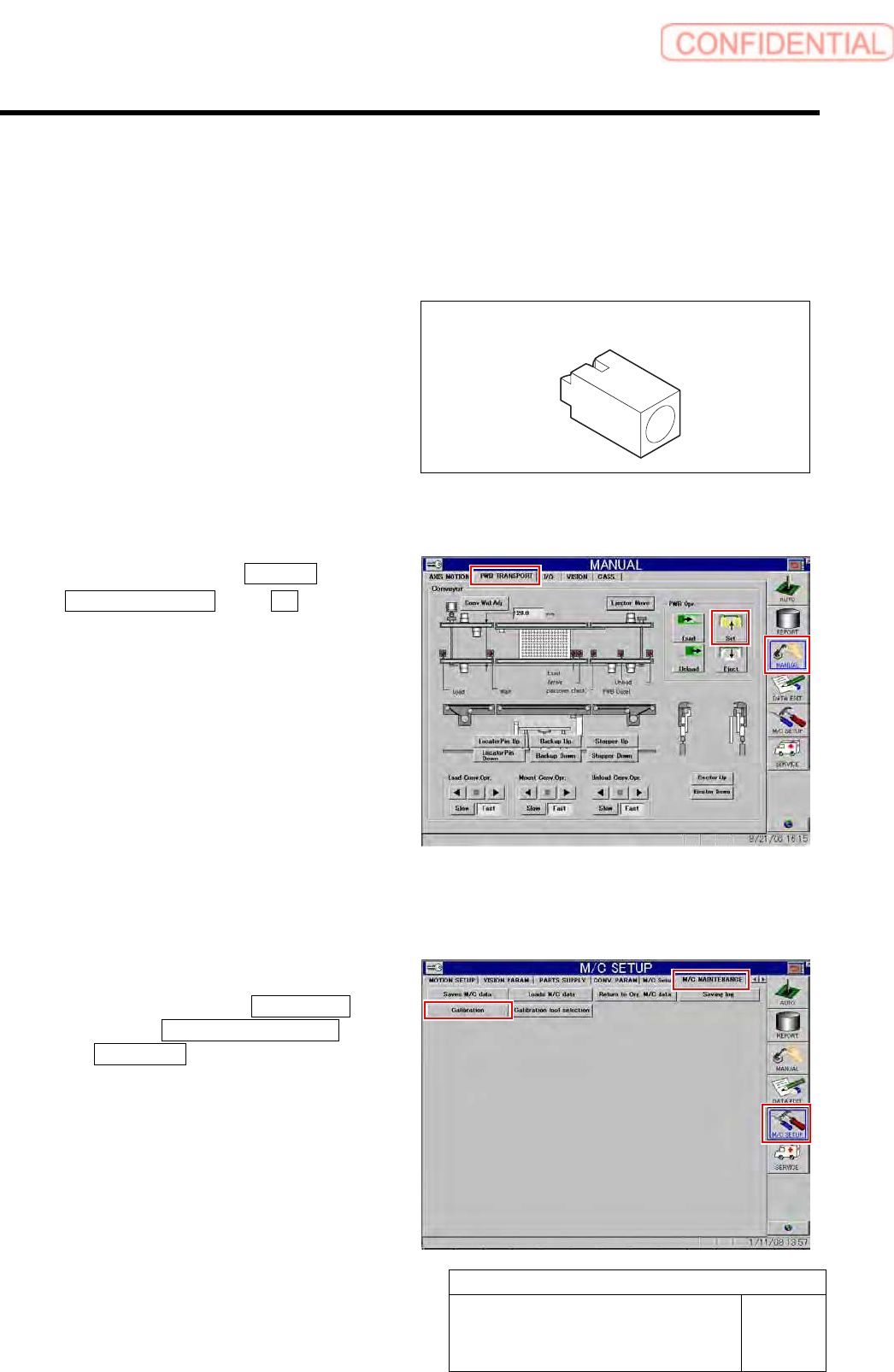
[Necessary jigs]
• RT origin jig
[Procedure]
1 Click in an order of MANUAL menu
PWB TRANSPORT tab Set button.
The backup plate rises.
2 Press the [ORG] button on the operation
panel to perform origin position return.
3 Display RT Axis Home screen.
1. Click in an order of M/C SETUP
menu M/C MAINTENANCE tab
Calibration button.
CALIBRATION screen is displayed.
RT origin jig