MAN00000772_SI-G200BB_SVCPDFA.pdf - 第169页
Set-up HLGB-10201-01 RT A xis Origin Position Set up SHEET 2/4 2. Click the Machin e Setup button on the CALIBRA TION screen. Machine Setup screen is d isplayed. 3. Click the RT Axis Home button on the Machine Setup scre…
Set-up
HLGB-10201-01
RT Axis Origin Position Setup
SHEET
1/4
RT Axis Origin Position Setup
Perform this working on both heads on the front side and rear side.
[Necessary jigs]
• RT origin jig
[Procedure]
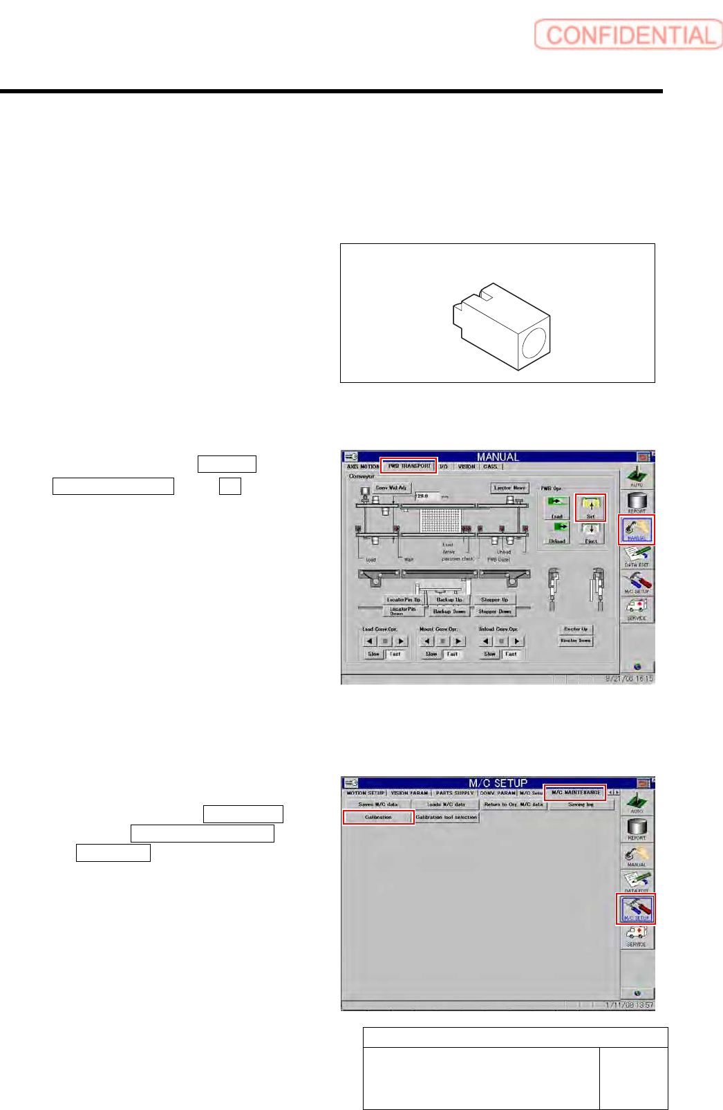
1 Click in an order of MANUAL menu
PWB TRANSPORT tab Set button.
The backup plate rises.
2 Press the [ORG] button on the operation
panel to perform origin position return.
3 Display RT Axis Home screen.
1. Click in an order of M/C SETUP
menu M/C MAINTENANCE tab
Calibration button.
CALIBRATION screen is displayed.
RT origin jig
Set-up
HLGB-10201-01
RT Axis Origin Position Setup
SHEET
2/4
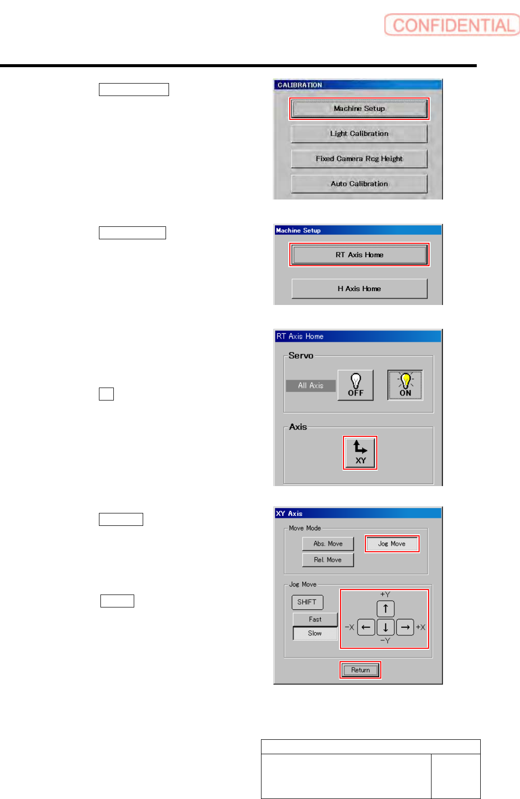
2. Click the Machine Setup button on the
CALIBRATION screen.
Machine Setup screen is displayed.
3. Click the RT Axis Home button on the
Machine Setup screen.
RT Axis Home screen is displayed.
4 Use the XY move screen to move the head
to a position where working is easily
performed.
1. Click the XY button on the RT Axis
Home screen.
XY Axis screen is displayed.
2. Click the Jog Move button in the move
mode.
3. Press the cursor key to move the head
to a position where working is easily
performed.
4. Press the Return button after the
head moves to close the XY axis
screen.
Set-up
HLGB-10201-01
RT Axis Origin Position Setup
SHEET
3/4
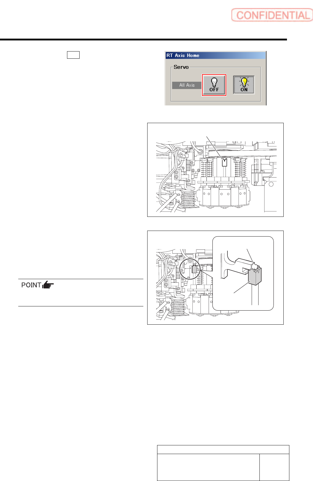
5 Click the servo OFF button to turn off the
servos for all axes.
6 Remove the spring holder and spring for
turret No.1 and put the RT origin jig on the
upper part of the inner shaft.
7 Put the H axis cam follower on the RT origin
jig.
Slightly lower the H axis with the cam follower being
on the RT origin jig to avoid positional deviation.
Be careful not to enter H axis OT and rotate the
RT axis.
RT origin jig
RT origin jig
H axis cam follower