MAN00000772_SI-G200BB_SVCPDFA.pdf - 第173页
Set-up HLGB-10202-01 H A xis Origin Position Setu p SHEET 2/4 3. Click the H Axis Home button on the Machine Setup screen. H Axis Home screen is displayed. 4 Use the XY move scre en to move the head to a position where w…
Set-up
HLGB-10202-01
H Axis Origin Position Setup
SHEET
1/4
H Axis Origin Position Setup
Perform this working on both heads on the front side and rear side.
[Necessary jigs]
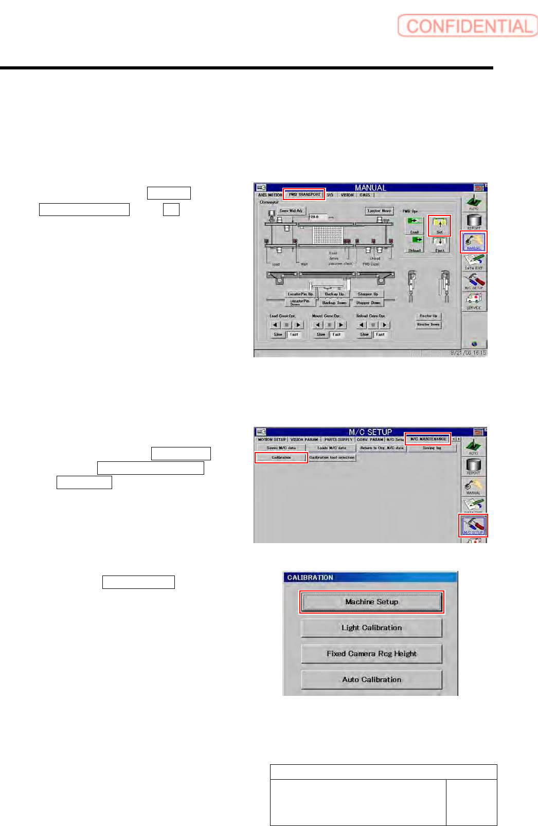
1 Click in an order of MANUAL menu
PWB TRANSPORT tab Set button.
The backup plate rises.
2 Press the [ORG] button on the operation
panel to perform origin position return.
3 Display H Axis Home screen.
1. Click in an order of M/C SETUP
menu M/C MAINTENANCE tab
Calibration button.
CALIBRATION screen is displayed.
2. Click the Machine Setup button on the
CALIBRATION screen.
Machine Setup screen is displayed.
Set-up
HLGB-10202-01
H Axis Origin Position Setup
SHEET
2/4
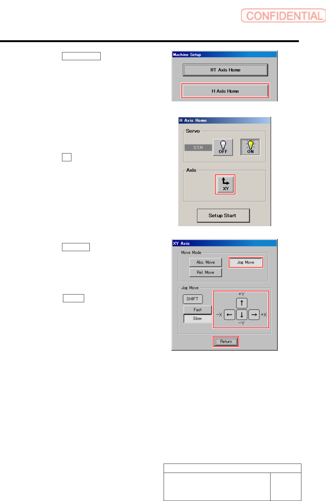
3. Click the H Axis Home button on the
Machine Setup screen.
H Axis Home screen is displayed.
4 Use the XY move screen to move the head
to a position where working is easily
performed.
1. Click the XY button on the H Axis
Home screen.
XY Axis screen is displayed.
2. Click the Jog Move button in the move
mode.
3. Press the cursor key to move the head
to a position where working is easily
performed.
4. Press the Return button after the
head moves to close the XY axis
screen.
Set-up
HLGB-10202-01
H Axis Origin Position Setup
SHEET
3/4
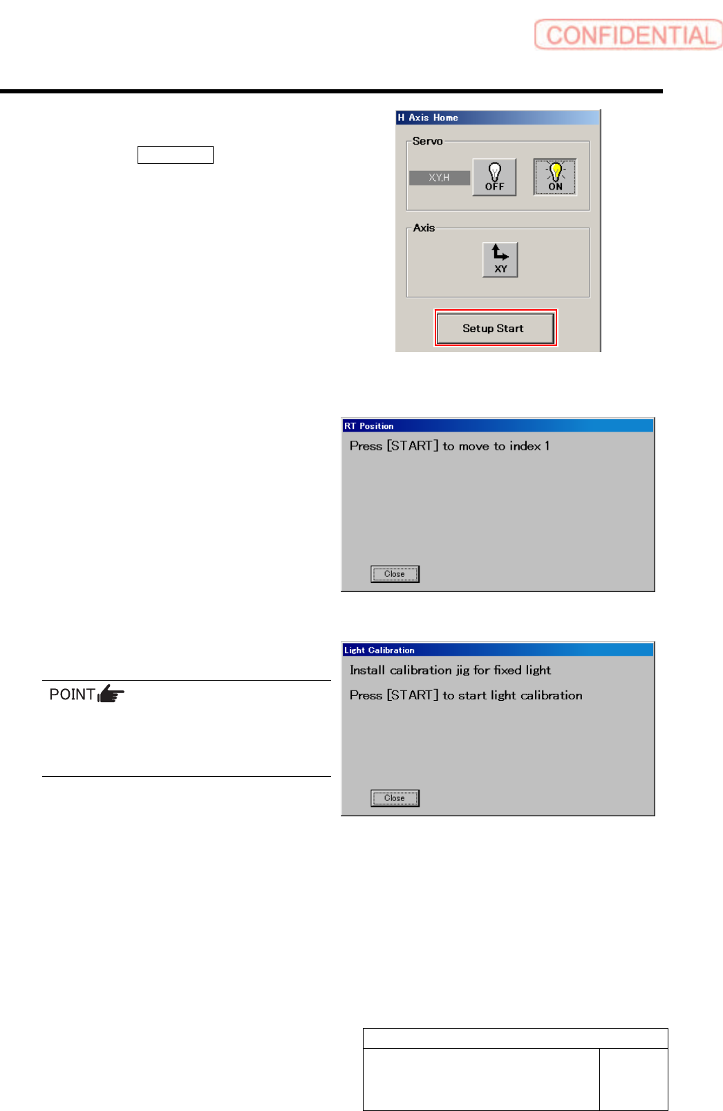
5 Set up H Axis Origin Position.
1. Click the Setup Start button on the H
Axis Home screen.
“Press [START] to move to index 1” is displayed
on the message screen.
2. Press the [START] button on the
operation panel.
The inner shaft of the turret No.1 moves to just
below H axis pusher, then “When [START]
button is pressed, captures H height and moves to
the next index” is displayed on the message
screen.
And, the servo is automatically turned OFF.
3. Lower the H axis roller by hand and
gradually return it to the top end.
After returning the H axis, push up the inner
shaft from lower section by finger and check
that the inner shaft has returned to the
uppermost end.
4. Press the [START] button on the
operation panel.
H axis standby position is automatically
captured, and “When [START] button is pressed,
moves to Index 2” is displayed on the message
screen.
5. Repeat working of the procedure 2.-4.
up to the turret No.8.