MAN00000772_SI-G200BB_SVCPDFA.pdf - 第176页
Set-up HLGB-10203-01 Acquiring Mounting S troke Setup SHEET 1/5 Acquiring Mounting S troke Setup Perform this working on both heads on the front sid e and rear side. [Necessary jigs] A Calibration plate jig B Jig positio…
Set-up
HLGB-10202-01
H Axis Origin Position Setup
SHEET
4/4
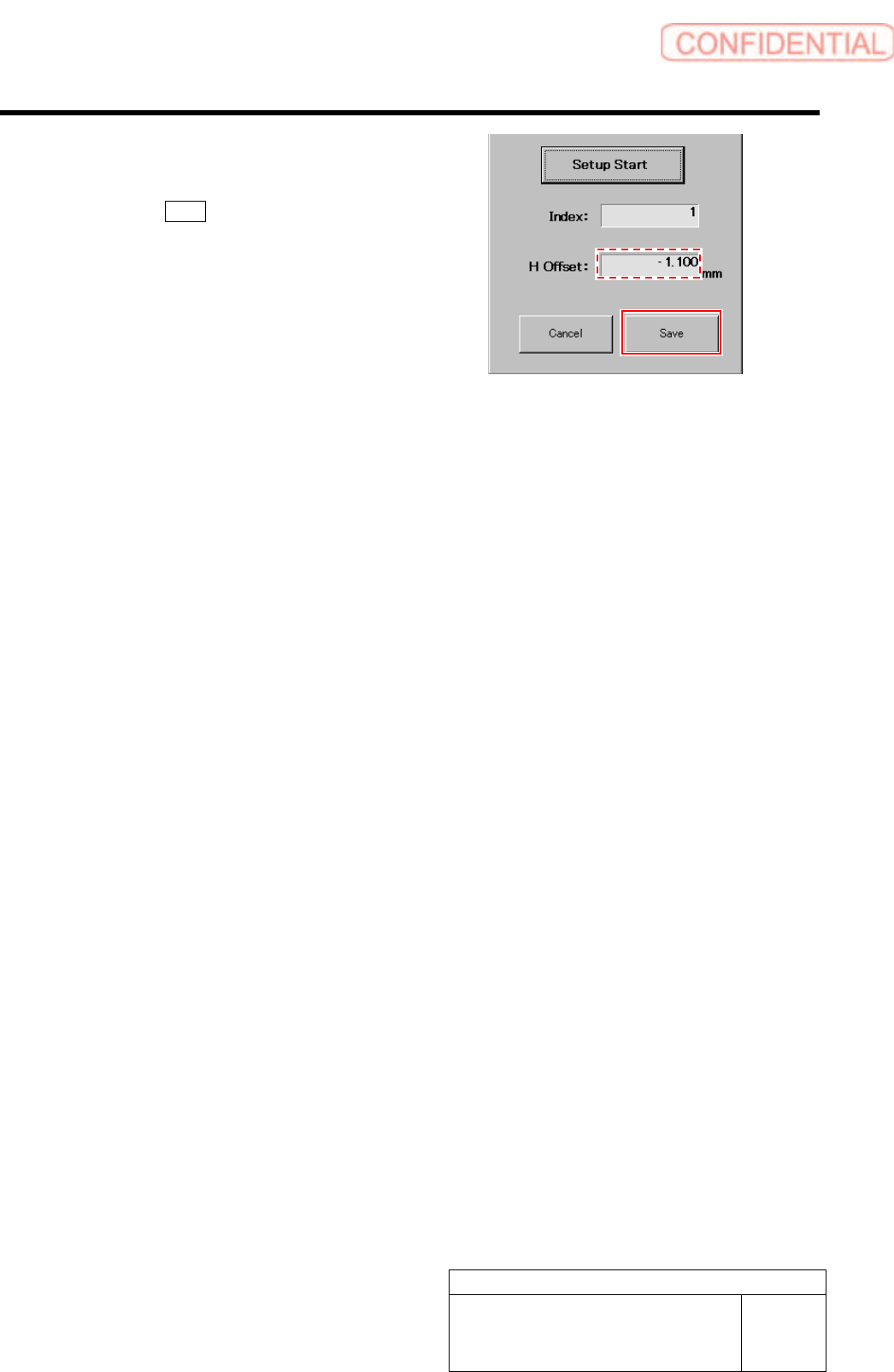
6 Check that numeric value is displayed in the
“H Offset” box on the H axis origin screen,
and click the Save button.
The H axis origin position is saved and H Axis Home
screen closes.
Set-up
HLGB-10203-01
Acquiring Mounting Stroke Setup
SHEET
1/5
Acquiring Mounting Stroke Setup
Perform this working on both heads on the front side and rear side.
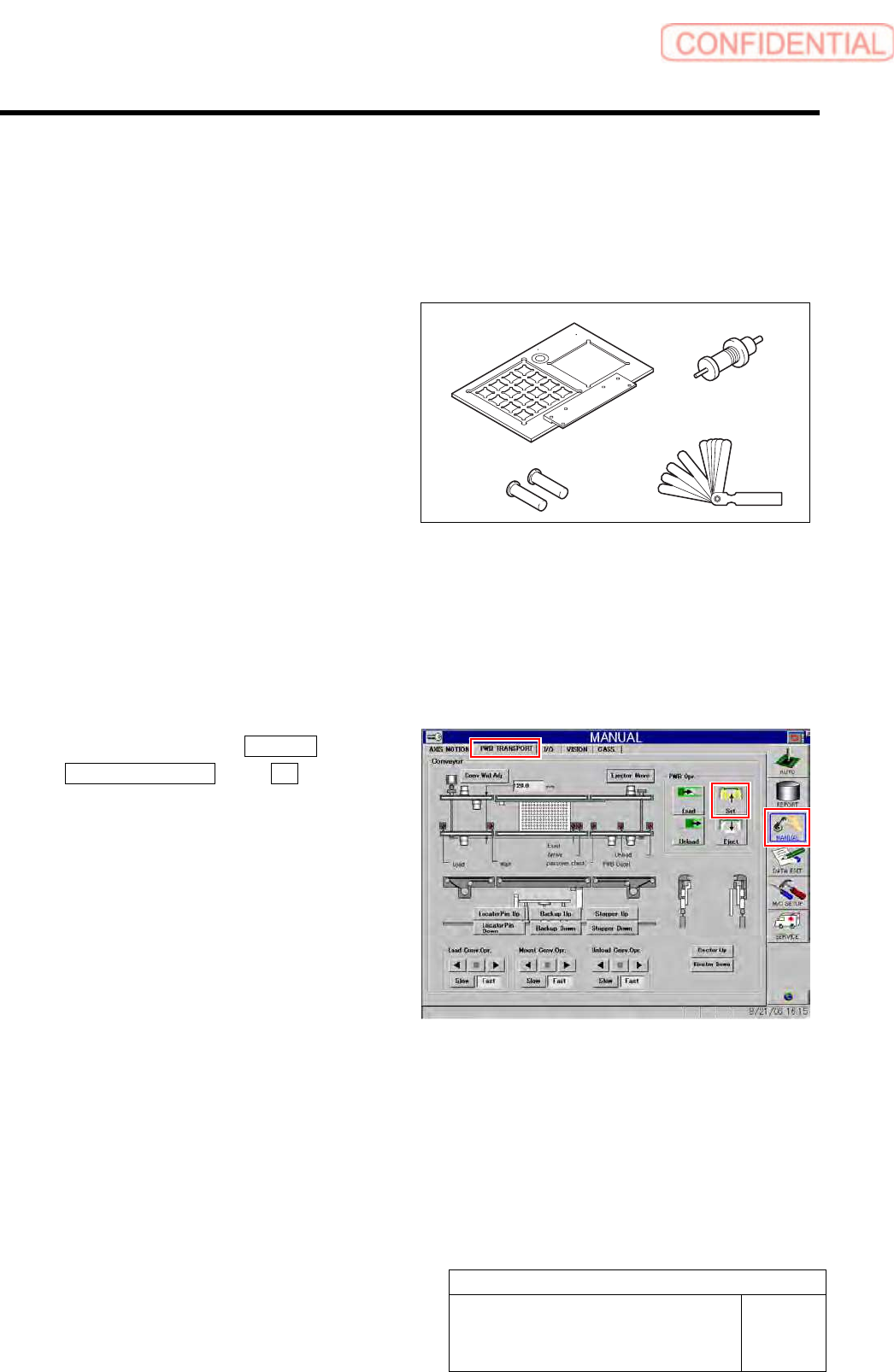
[Necessary jigs]
A Calibration plate jig
B Jig positioning pin
C Length reference nozzle jig
D Thickness gauge (t=0.03 mm)
[Procedure]
1 Install the calibration plate jig.
For mounting method of the calibration plate jig, refer to “Install the Calibration Plate Jig [HLGB-10101-01]”.
2 Click in an order of MANUAL menu
PWB TRANSPORT tab Set button.
The backup plate rises.
3 Press the [ORG] button on the operation
panel to perform origin position return.
A
BD
C
Set-up
HLGB-10203-01
Acquiring Mounting Stroke Setup
SHEET
2/5
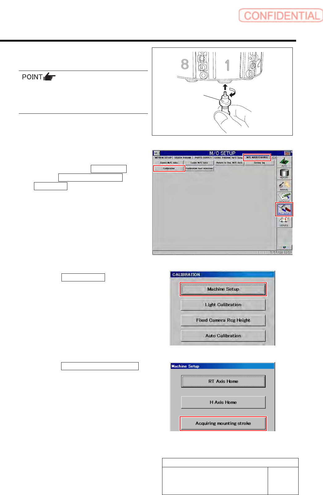
4 Install the length reference nozzle jig to the
turret No.1.
When installing the nozzle, insert it while
slowly turning.
After inserting the nozzle, check that it is not
drawn out by pulling downward.
5 Display Acquiring mounting stroke screen.
1. Click in an order of M/C SETUP
menu M/C MAINTENANCE tab
Calibration button.
CALIBRATION screen is displayed.
2. Click the Machine Setup button on the
CALIBRATION screen.
Machine Setup screen is displayed.
3. Click the Acquiring mounting stroke
button on the Machine Setup screen.
Acquiring mounting stroke screen is displayed.
Length reference
nozzle jig