MAN00000772_SI-G200BB_SVCPDFA.pdf - 第187页
Set-up HLGB-10205-01 Fiducial Mark Setup SHEET 3/3 Jog-move the head part until the locator pin is displayed on the center of the PCBOARD DISPLA Y screen. * A section displayed in white on the PCBOARD DISPLA Y screen is …
Set-up
HLGB-10205-01
Fiducial Mark Setup
SHEET
2/3
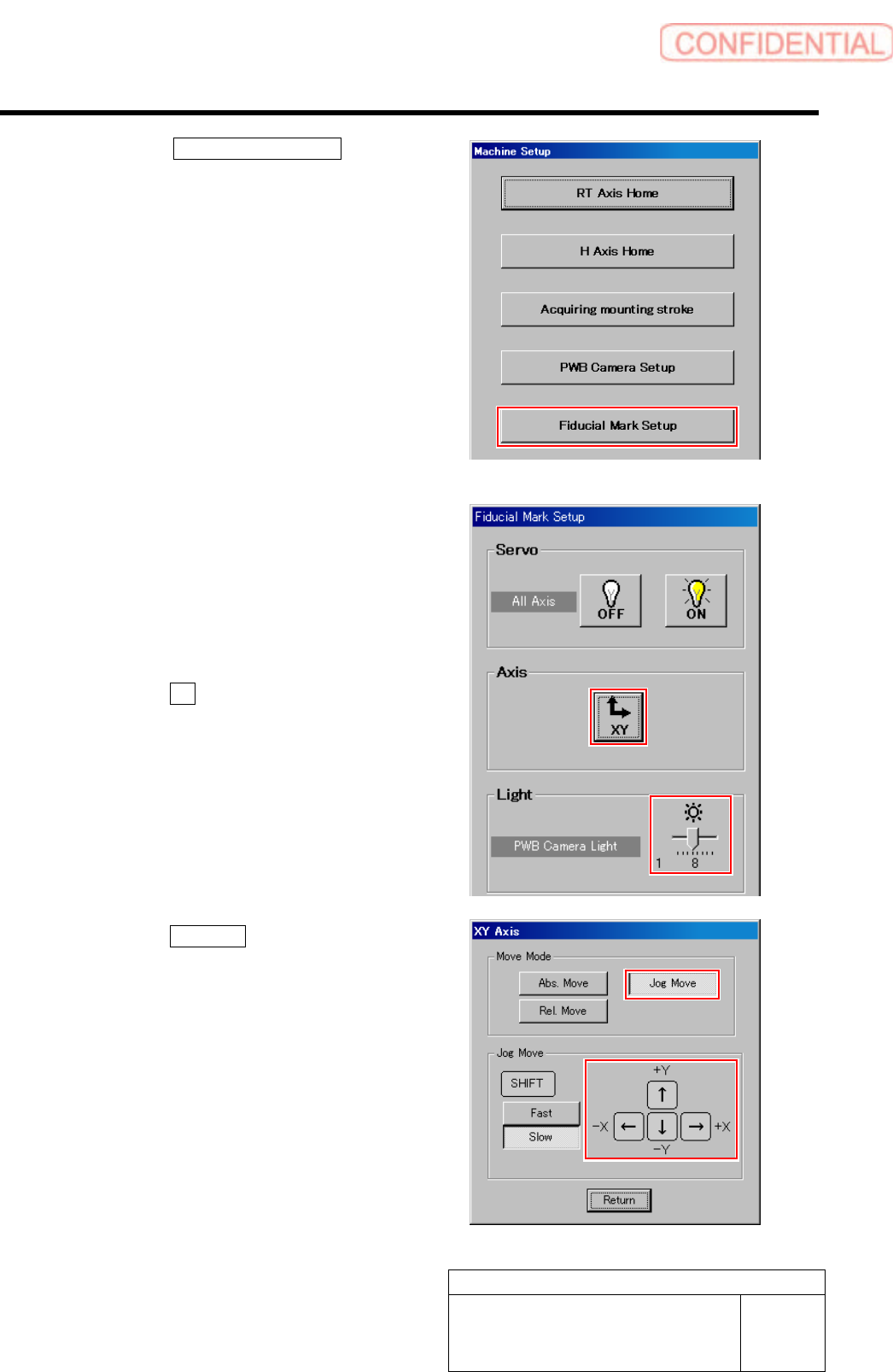
4. Click the Fiducial Mark Setup button
on the Machine Setup screen.
Fiducial Mark Setup screen is displayed.
5 Set brightness of the PWB camera light to
“6” or “7”.
6 Move the PWB camera onto the locator pin
while checking the PCBOARD DISPLAY
screen.
1. Click the XY button on the Fiducial
Mark Setup screen.
XY Axis screen is displayed.
2. Click the Jog Move button.
3. Press the cursor key to jog-move the
reference camera onto the locator pin.
Set-up
HLGB-10205-01
Fiducial Mark Setup
SHEET
3/3
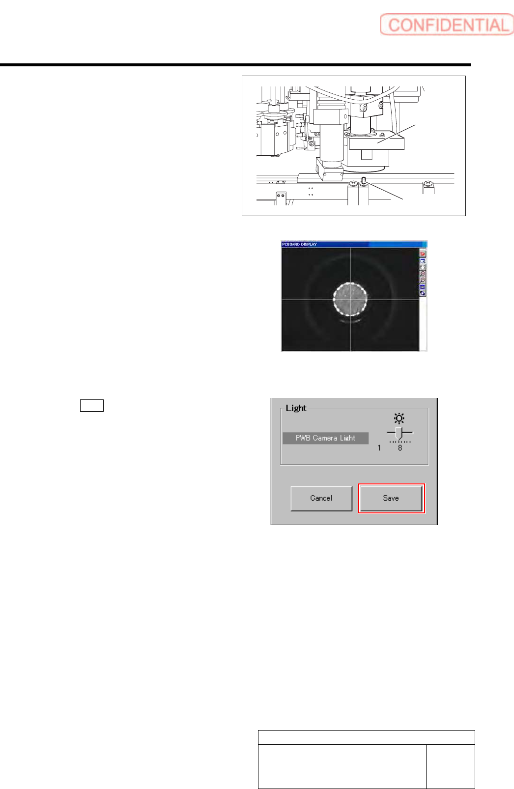
Jog-move the head part until the locator pin is
displayed on the center of the PCBOARD
DISPLAY screen.
* A section displayed in white on the PCBOARD
DISPLAY screen is locator pin.
7 Click the Save button on the Fiducial Mark
Setup screen.
The present position is saved and the RT Axis Home
screen closes.
Locator Pin
PWB camera
Set-up
HLGB-10206-01
F Axis Setup
SHEET
1/5
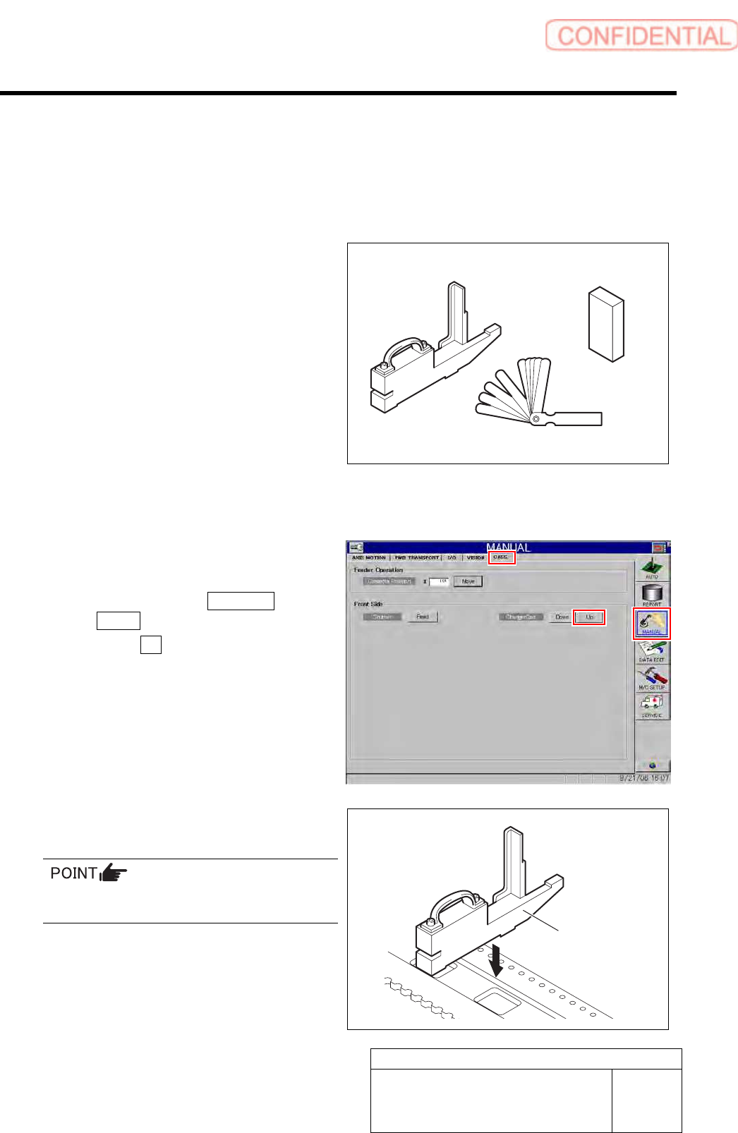
F Axis Setup
Perform this working on respective F axis on the front side and rear side.
[Necessary jigs]
• Feed adjusting jig
• Part feed height jig
• Thickness gauge
[Procedure]
1 Set the replacing carrier.
1. Set the replacing carrier on the unit.
2. Click in an order of MANUAL menu
CASS. tab.
3. Click the Up button for the replacing
carrier on the front or rear side.
4. Press the [START] button on the
operation panel.
The cassette table on the replacing carrier is
locked.
2 Set the feed adjusting jig to the No.20
position on the cassette table.
There should be no gap between the feed
adjusting jig and the cassette table.
Feed adjusting jig
Part feed height jig
Thickness gauge
Feed adjusting jig