MAN00000772_SI-G200BB_SVCPDFA.pdf - 第193页
Set-up HLGB-10207-01 RN A xis Origin Offset Setup SHEET 1/4 RN Axis Origin Of fset Setup Perform this working on both heads on the front sid e and rear side. [Procedure] 1 Set the RN of fset to “0”. 1. Click in an order …
Set-up
HLGB-10206-01
F Axis Setup
SHEET
5/5
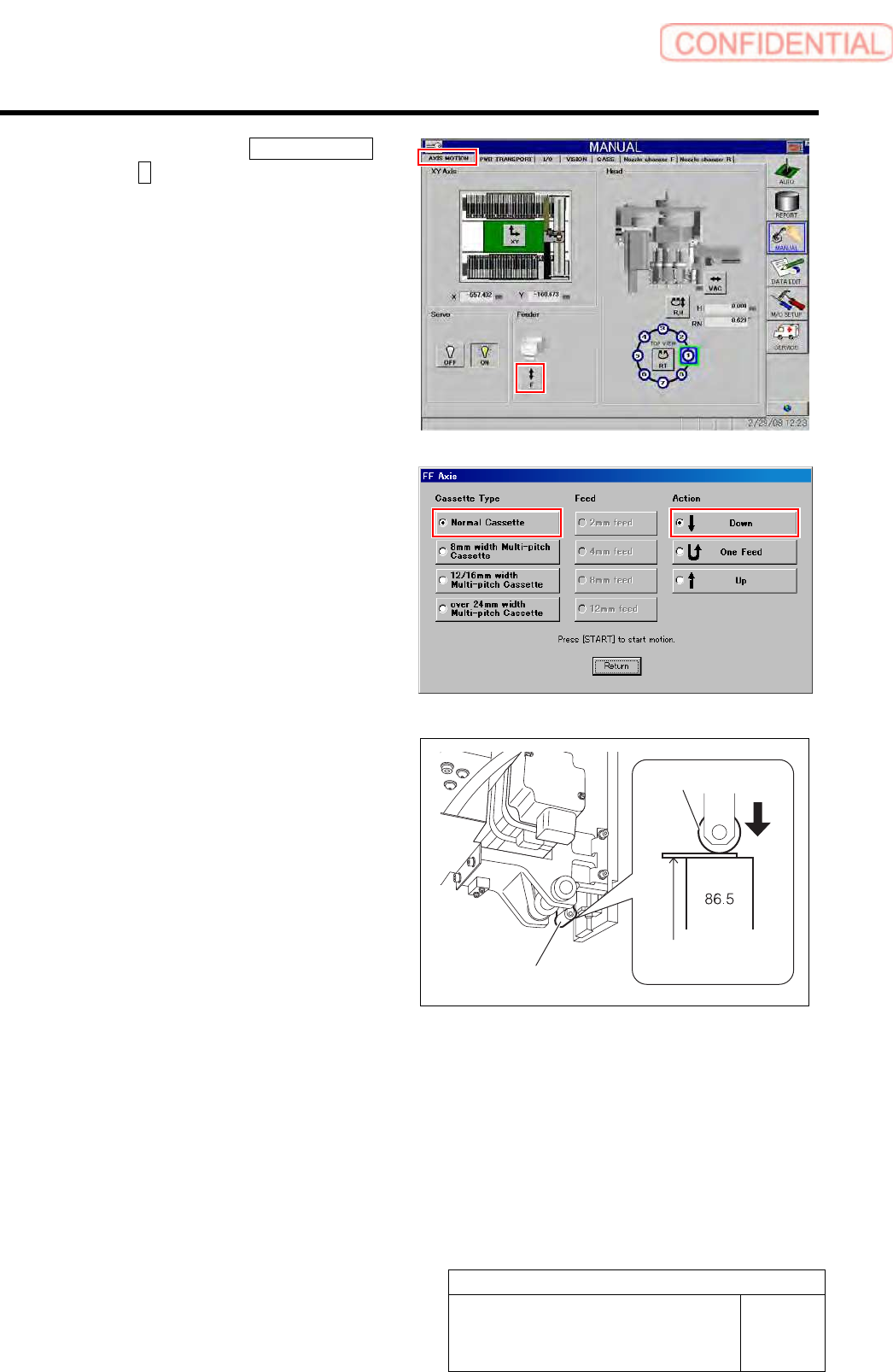
5. Click in an order of AXIS MOTION
tabF button.
FF Axis screen is displayed.
6. Place a check in “Normal Cassette”
and “Down” and press the [START]
button on the operation panel.
The feed roller lowers.
7. Check that clearance between the
parts feed height jig (86.5mm) and the
feed roller is in a range of 0<0.2mm
with a thickness gauge.
8. After checking, place a check in the
“Up” on the FF axis careen, and press
the [START] button.
13 Also check the height of the F axis on the rear side by the same procedure as in the procedure 12.
Feed roller
Feed roller
Thickness gauge
Set-up
HLGB-10207-01
RN Axis Origin Offset Setup
SHEET
1/4
RN Axis Origin Offset Setup
Perform this working on both heads on the front side and rear side.
[Procedure]
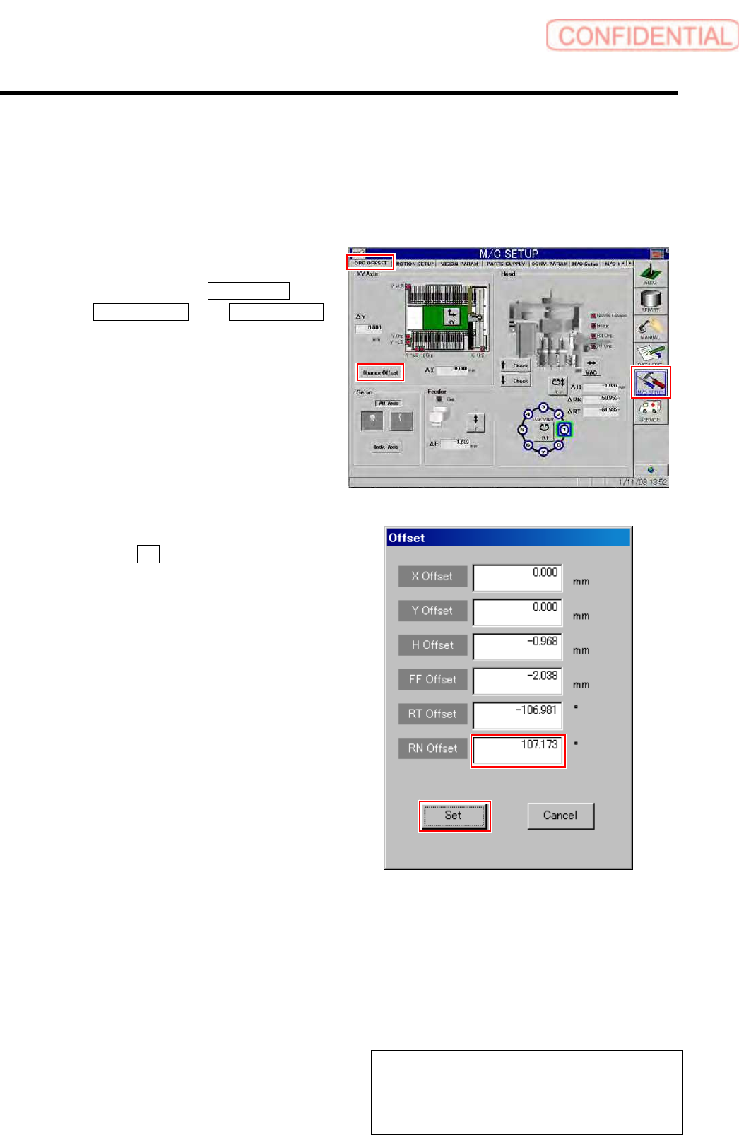
1 Set the RN offset to “0”.
1. Click in an order of M/C SETUP menu
ORG OFFSET tabChange Offset
button.
Change Offset screen is displayed.
2. Input “0” in the RN Offset box, and
click the Set button.
RN offset value is set to “0”.
Set-up
HLGB-10207-01
RN Axis Origin Offset Setup
SHEET
2/4
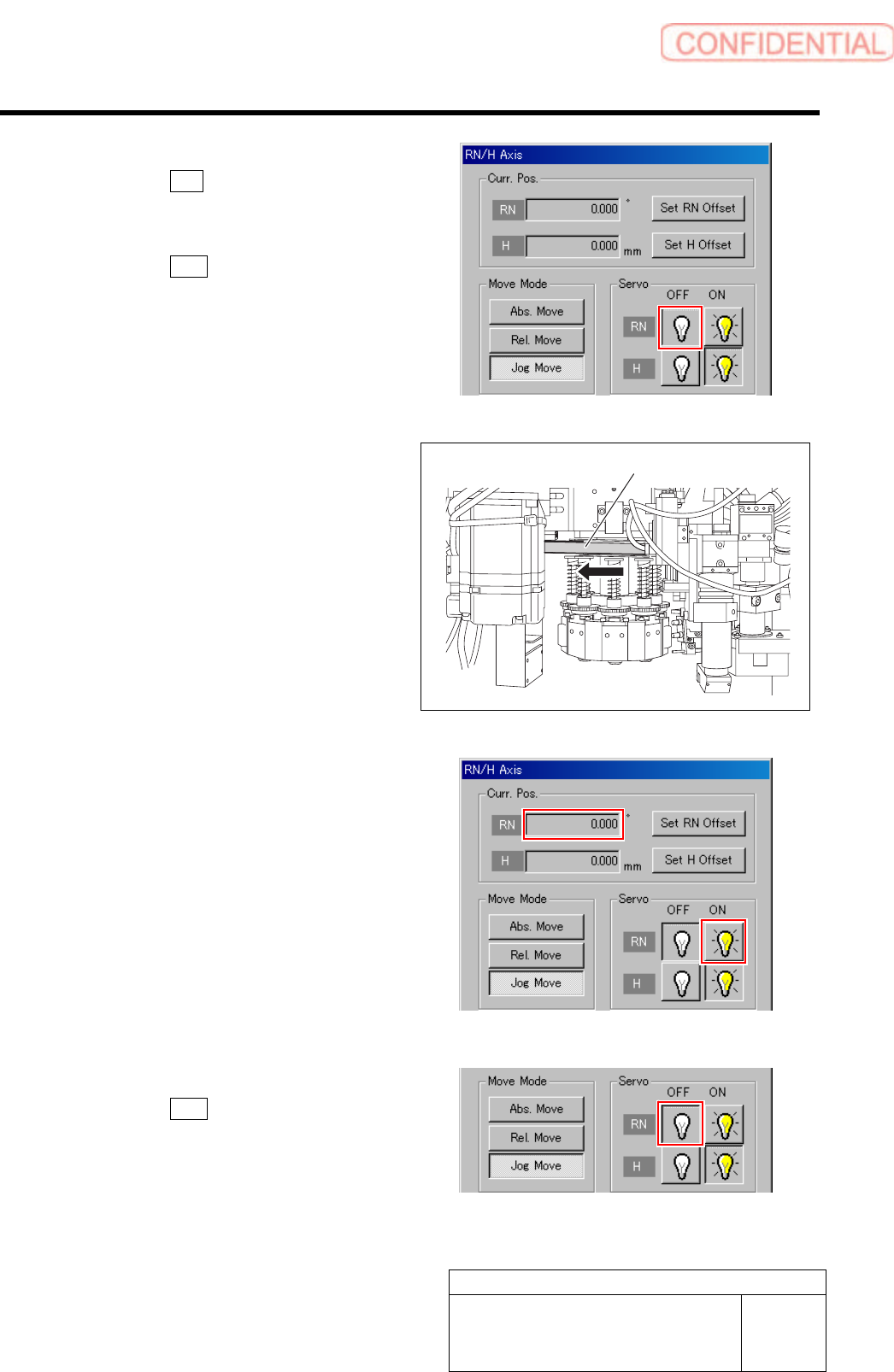
2 Turn off the servo for RN axis.
1. Click the R.H button on the ORG
OFFSET screen.
RN/H Axis screen is displayed.
2. Click the OFF button for the RN axis
servo.
3 Check the rotating angle when rotating the
RN axis belt clockwise.
1. Turn on the servo for the RN axis at a
position where the RN axis is rotated
clockwise and stops.
2. Take note of angle of the RN axis
displayed on the RN/H Axis screen.
(Example: 369.7˚)
4 Turn off the servo for RN axis.
1. Click the OFF button for the RN axis
servo on the RN/H Axis screen.
RN axis belt