MAN00000772_SI-G200BB_SVCPDFA.pdf - 第200页
Set-up HLGB-10208-01 Pickup Check Camera Setu p SHEET 4/5 2. Loosen the locknut f or the absorber . 8 7 6 3. Click the ↓ Check button on the origin offset screen to low er the Pickup check camera. 4. T urn the absorber t…
Set-up
HLGB-10208-01
Pickup Check Camera Setup
SHEET
3/5
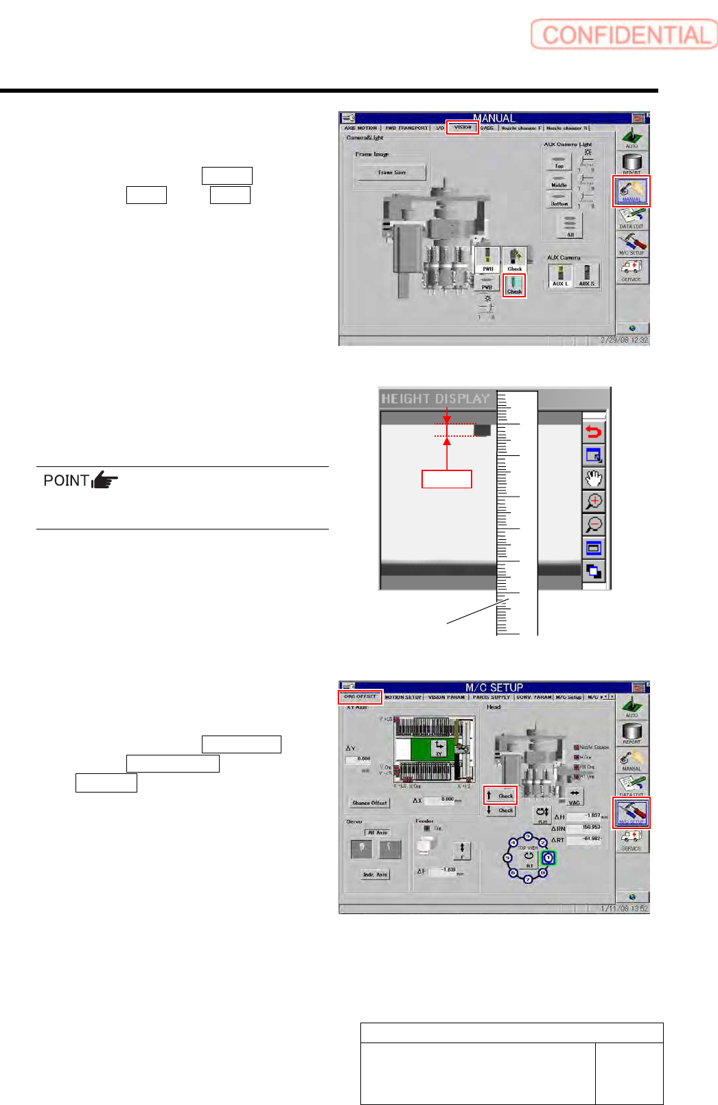
4 Check length of nozzle end displayed on the
HEIGHT DISPLAY screen.
1. Click in an order of Manual
menuVision tab Check button.
Jig nozzle end is displayed on the HEIGHT
DISPLAY screen.
2. Apply a scale on the screen to check
that length of the displayed jig nozzle
end is 3.0mm.
For actual dimension of the nozzle, end of 1mm
is displayed on the screen.
5 Adjust the absorber if the nozzle length on
the HEIGHT DISPLAY screen is not 3.0mm.
1. Click in an order of M/C SETUP
menuORG OFFSET tab
↑ Check button to raise the Pickup
check camera.
Scale
3.0mm
Set-up
HLGB-10208-01
Pickup Check Camera Setup
SHEET
4/5
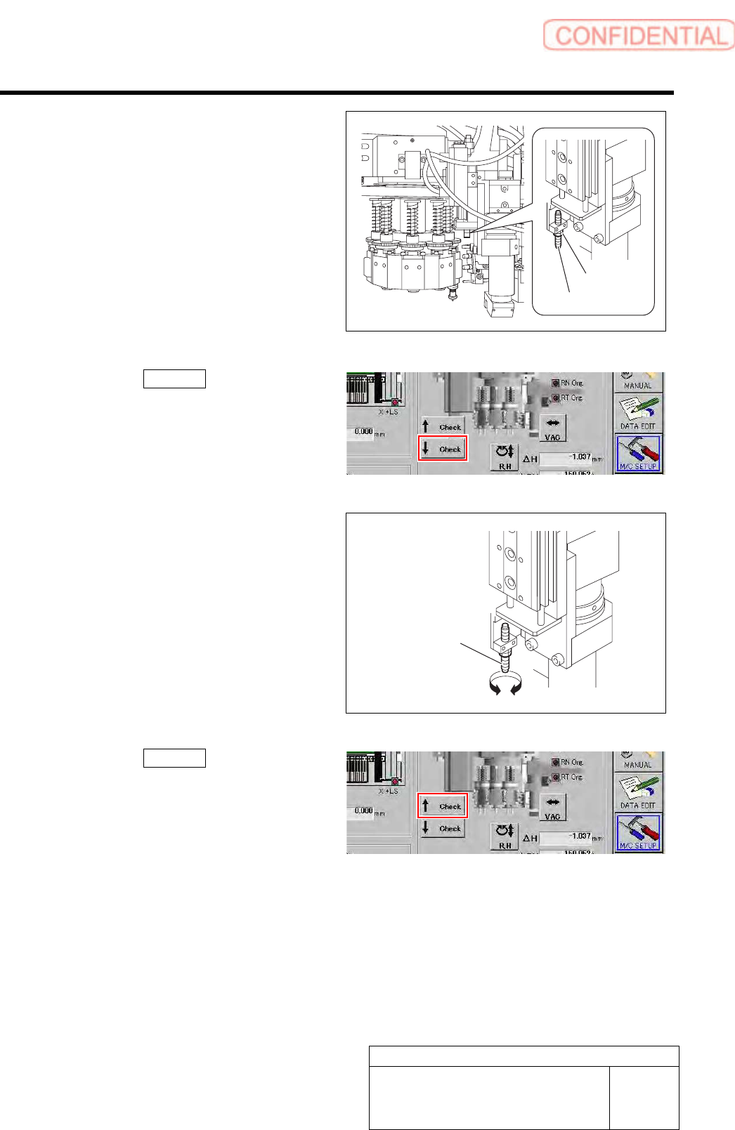
2. Loosen the locknut for the absorber.
8
7
6
3. Click the ↓ Check button on the
origin offset screen to lower the Pickup
check camera.
4. Turn the absorber to adjust the
protrusion amount.
5. Click the ↑ Check button on the
origin offset screen to raise the Pickup
check camera again.
6. Tighten the locknut for the absorber.
A
bsorbe
r
Locknut
Absorbe
r
Set-up
HLGB-10208-01
Pickup Check Camera Setup
SHEET
5/5
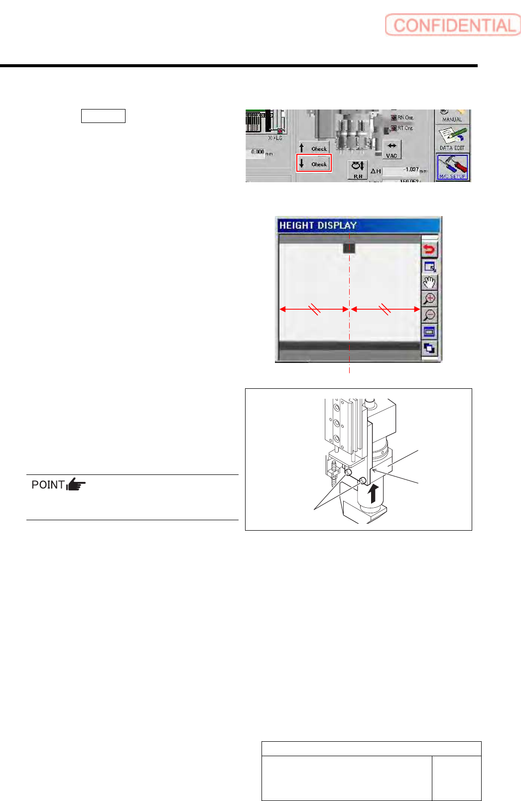
[Lateral alignment]
1 Click the ↓ Check button on the origin
offset screen to lower the Pickup check
camera.
2 Visually check that top end of the nozzle is
displayed on the center of the HEIGHT
DISPLAY screen.
3 Unless top end of the nozzle is on the center
of the window, loosen cap screws (2-CP4x8)
to adjust installing position of the check
camera.
Fix the Pickup check camera with pressing it
against upward.
4 Setup of the Pickup check camera is
completed.
1. Press the [ORG] button on the
operation panel to perform origin
position return.
2. Remove the length reference nozzle jig
from the turret No.1.
Cap screw
Press-against
location
Pickup check
camera