MAN00000772_SI-G200BB_SVCPDFA.pdf - 第211页
Calibration HLGB-10304-01 Auto Calibration (Recognition of relationship betw een PWB coordinate and mechanism coordinat e) SHEET 1/7 Auto Calibration (Recognition of relationship between PWB coordinate and mec hanism coo…
Calibration
HLGB-10303-01
Light calibration for Global
Recognition
SHEET
3/3
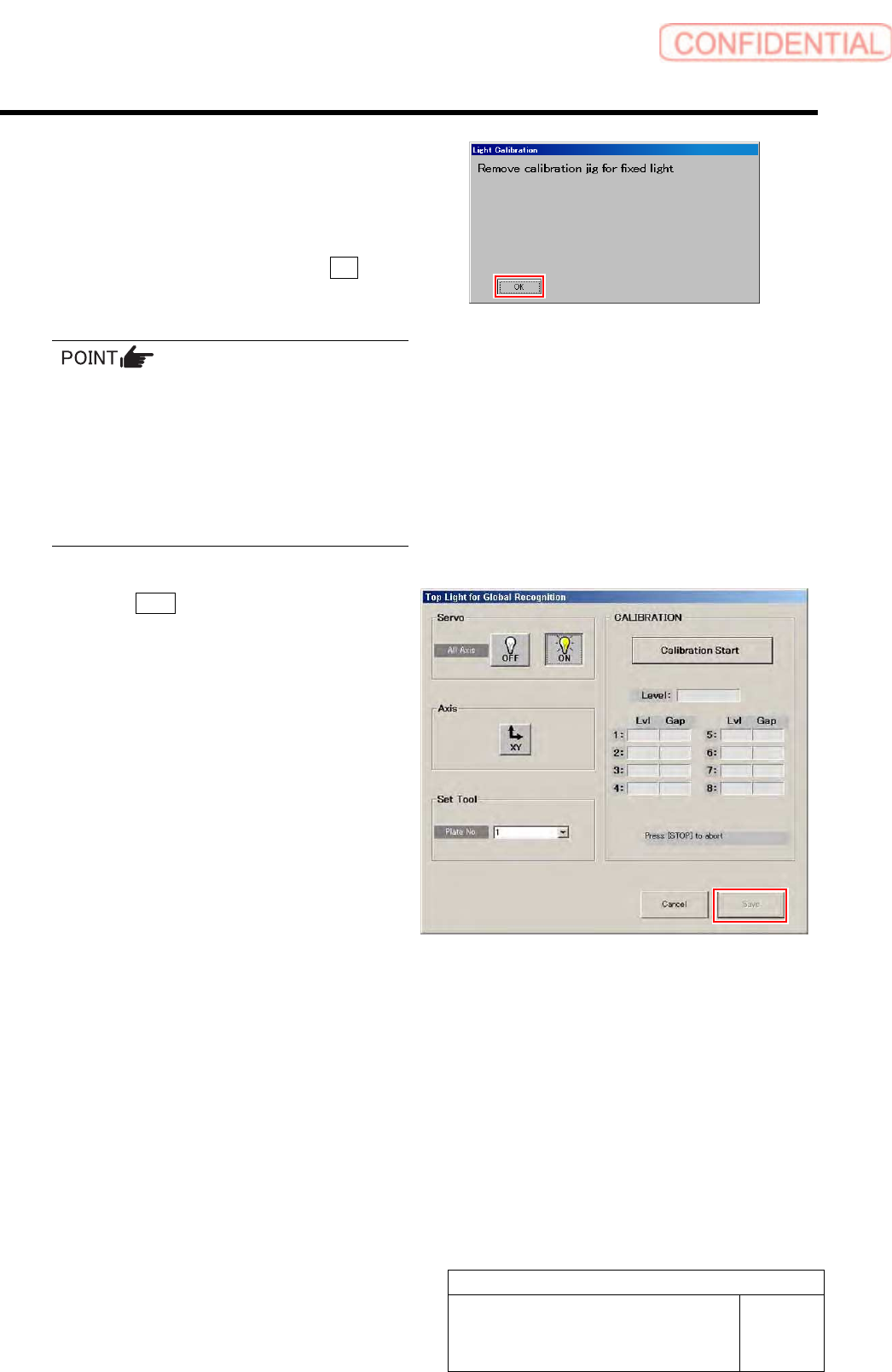
After a few minutes, the calibration ends, and
“Remove calibration jig for fixed light” is
displayed on the message screen.
2. Remove the fixed camera light
calibration jig and the reflection
intensity spacer and click the OK
button.
・ When subsequently performing calibrations
of Middle Light for Global Recognition/
Bottom Light for Global Recognition/ Coaxial
Light for Global Recognition, it is
unnecessary to remove the jig.
・ When ending calibration, be careful of
forgetting to leave the reflection intensity
spacer.
6 Click the Save button.
GAP values of Lvl 1~8 are saved and Top Light for
Global Recognition is ended.
7 Perform calibrations of Middle Light for
Global Recognition/ Bottom Light for Global
Recognition/ Coaxial Light for Global
Recognition by the same procedure.
Calibration
HLGB-10304-01
Auto Calibration (Recognition of
relationship between PWB coordinate and
mechanism coordinate)
SHEET
1/7
Auto Calibration (Recognition of relationship between PWB
coordinate and mechanism coordinate)
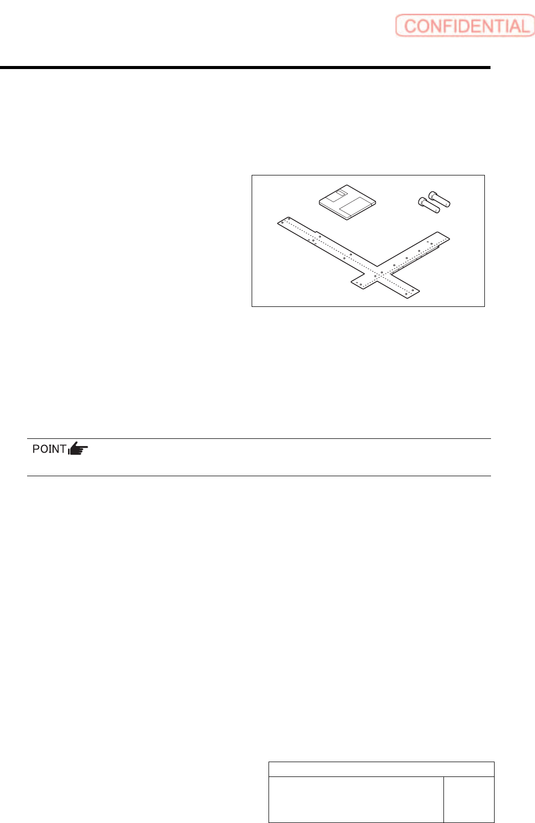
[Necessary jigs]
A Calibration data FD
B Ball point jig
C Positioning pins for ball point jig
[Procedure]
1 Load the calibration data.
For calibration data loading procedure, refer to “Calibration Data Load [HLGB-10105-01]”.
2 Change the software limit for Y-axis temporarily.
Make sure to take a note of the original value before changing it.
<To execute calibration with the front head>
1. Open “c:¥asm¥mcdata1¥ac_param.ini” with WordPad.
2. Add the absolute value 100 to “SOFT_LIMIT_PLUS” and “SOFT_LIMIT_MINUS” of
[AC_Y] respectively.
3. Save (overwrite) the file, and then restart the system.
<To execute calibration with the rear head>
1. Open “c:¥asm¥mcdata2¥ac_param.ini” with WordPad.
2. Add the absolute value 100 to “SOFT_LIMIT_PLUS” and “SOFT_LIMIT_MINUS” of
[AC_Y] respectively.
3. Save (overwrite) the file, and then restart the system.
C
B
A
Calibration
HLGB-10304-01
Auto Calibration (Recognition of
relationship between PWB coordinate and
mechanism coordinate)
SHEET
2/7
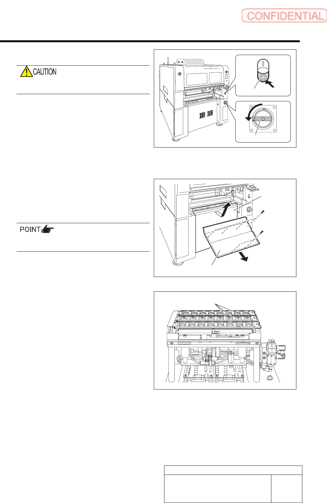
3 Shut off the power of the unit.
Do not shut down the power from the start
menu of Windows
®
.
1. Press the power off switch.
Shutting down of the system starts and the power
is automatically shut off.
2. Turn off the main breaker.
The power receiving lamp on the power panel
lights off.
4 Prepare to install the ball point jig.
1. Remove the Lower cover and the
shooter from the front and rear side of
the unit.
Tile the lower cover slightly toward you and pull
the fan cable to remove the lower panel.
2. Remove all the nozzle cartridges from
the rear side of the unit.
Lower cover
Shooter
Nozzle cartridges
Main breaker
Power off switch