MAN00000772_SI-G200BB_SVCPDFA.pdf - 第224页
Calibration HLGB-10306-01 Auto Calibration (Recog nition of Relationship for the Multiple Recognition) SHEET 3/4 2. Click the Recogn ition of relati onship for the Multi ple Recognition butt on on the Multi-fu nctional m…
Calibration
HLGB-10306-01
Auto Calibration (Recognition of
Relationship for the Multiple Recognition)
SHEET
2/4
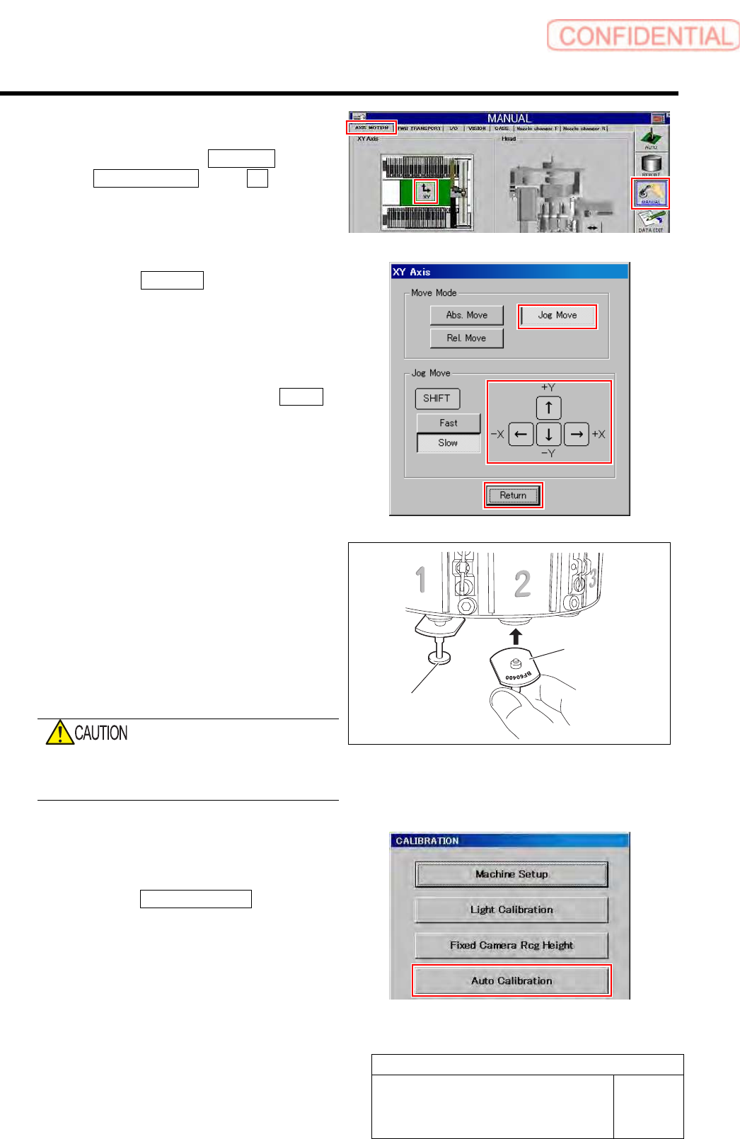
4 Move the head clear of the work area.
1. Click in an order of MANUAL menu
AXIS MOTION tab XY button.
XY Axis screen is displayed.
2. Click the Jog Move button in the move
mode.
3. Press the cursor key to move the head
to a position where working is easily
performed.
4. After moving the head, click the Return
button to close the XY axis screen.
5 Install the jig nozzles to head.
1. Install the BF00900 nozzles (1 piece)
to the turrets No.1.
2. Install the BF60400 nozzles (7 pieces)
to the turrets No.2~8.
Attach the nozzle so that the mark of the nozzle
type comes outer side of the turret.
Do not execute the automatic replacement of
the nozzle using the nozzle changer when the
calibration has not been completed.
6 Display a Recognition of relationship for
Multiple Recognition screen.
1. Click the Auto Calibration button on
the CALIBRATION screen.
Multi-functional machine calibration screen is
displayed.
BF60400 nozzle
BF00900 nozzle
Calibration
HLGB-10306-01
Auto Calibration (Recognition of
Relationship for the Multiple Recognition)
SHEET
3/4
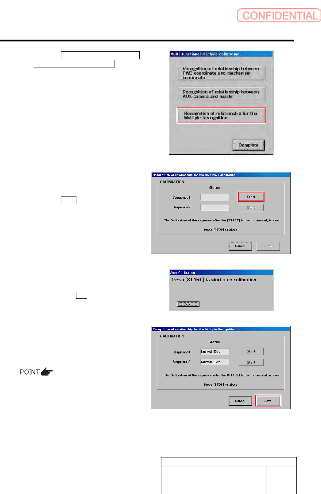
2. Click the Recognition of relationship
for the Multiple Recognition button on
the Multi-functional machine
calibration screen.
Recognition of relationship for Multiple
Recognition screen is displayed.
7 Start calibration of relationship for the
Multiple Recognition.
1. Click the Start button of Sequence 1.
2. Press the [START] button to start the
auto calibration.
Sequence after the Start button is clicked is
subsequently executed.
8 Check that it was normally ended, and click
the Save button.
Calibration result is saved.
If an error occurs and the process aborts, clean
the jig chips and then restart the calibration
from Sequence 1.
Calibration
HLGB-10306-01
Auto Calibration (Recognition of
Relationship for the Multiple Recognition)
SHEET
4/4
9 End auto calibration.
1. If the recognition of relationship between PWB coordinate and mechanism coordinate has
been performed in advance of this procedure, return the software limit for Y-axis to the
original value.
2. Remove the jig chips, calibration plate, and the jig nozzles.
After ending automatic calibration, perform nozzle changer teaching.
For nozzle changer teaching procedure, refer to “Nozzle Changer Teaching [HLGB-10307-01]”.