MAN00000772_SI-G200BB_SVCPDFA.pdf - 第228页
Calibration HLGB-10307-01 Nozzle Changer T eaching SHEET 3/5 7 Display a Nozzle Chang er Global T eachi ng screen. 1. Click in an order of M/ C SETUP menu MOTION SETUP tab Nozzle changer tab. 2. Click the T eaching b…
Calibration
HLGB-10307-01
Nozzle Changer Teaching
SHEET
2/5
4 Move the head clear of the work area.
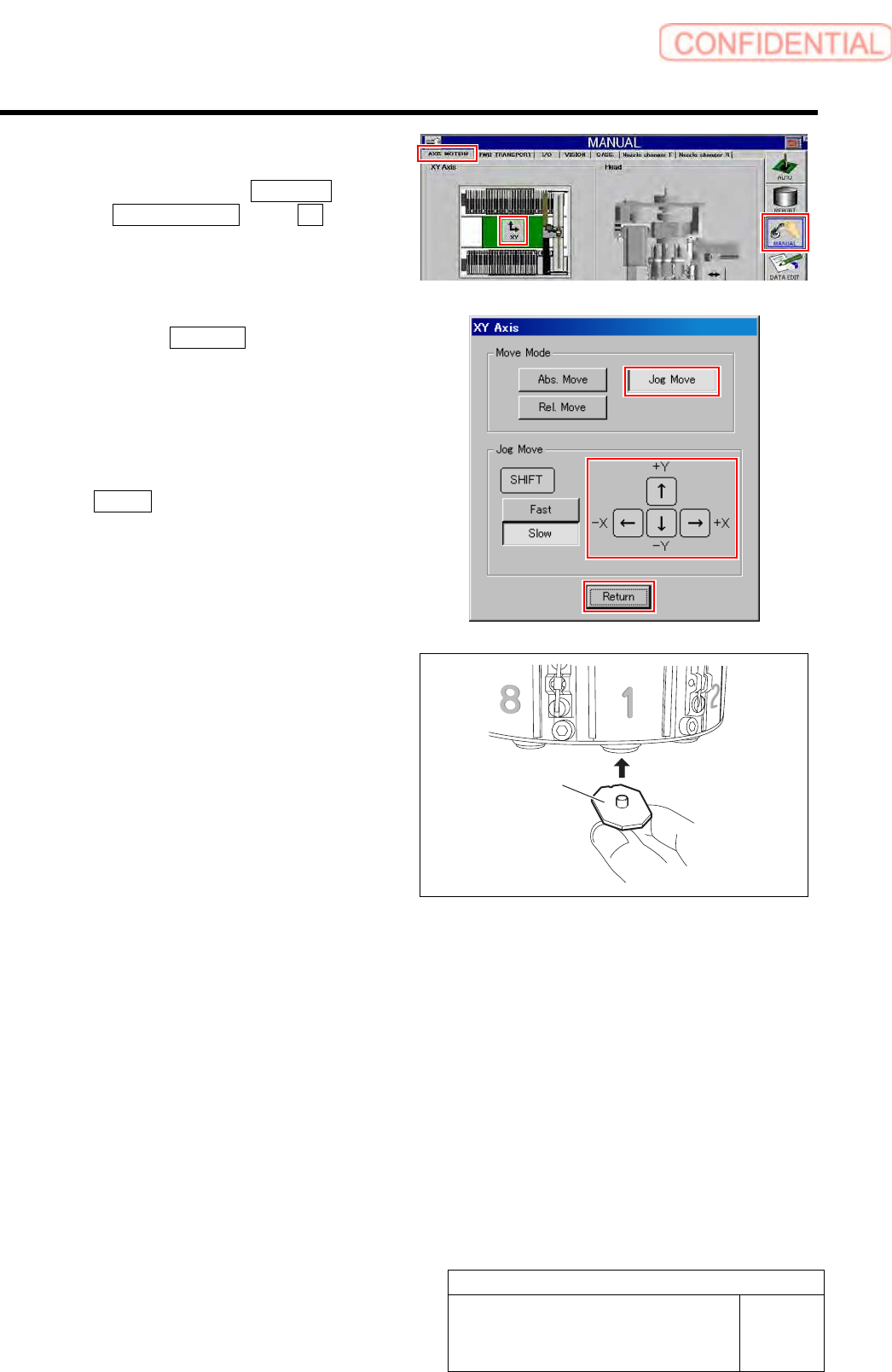
1. Click in an order of MANUAL menu
AXIS MOTION tab XY button.
XY Axis screen is displayed.
2. Click the Jog Move button in the move
mode.
3. Press the cursor key to move the head
to a position where working is easily
performed.
4. After moving the head, click the
Return button to close the XY axis
screen.
5 Install the jig nozzle for nozzle changer to
the turret No.1.
Attach the jig nozzle so that its notch comes inward of
the turret.
6 Make sure turret No.1 is under the H-axis.
If the position is deviated, move the turret No.1 to
under the H axis on the operation screen for the RT
axis.
Jig nozzle fo
r
nozzle changer
Calibration
HLGB-10307-01
Nozzle Changer Teaching
SHEET
3/5
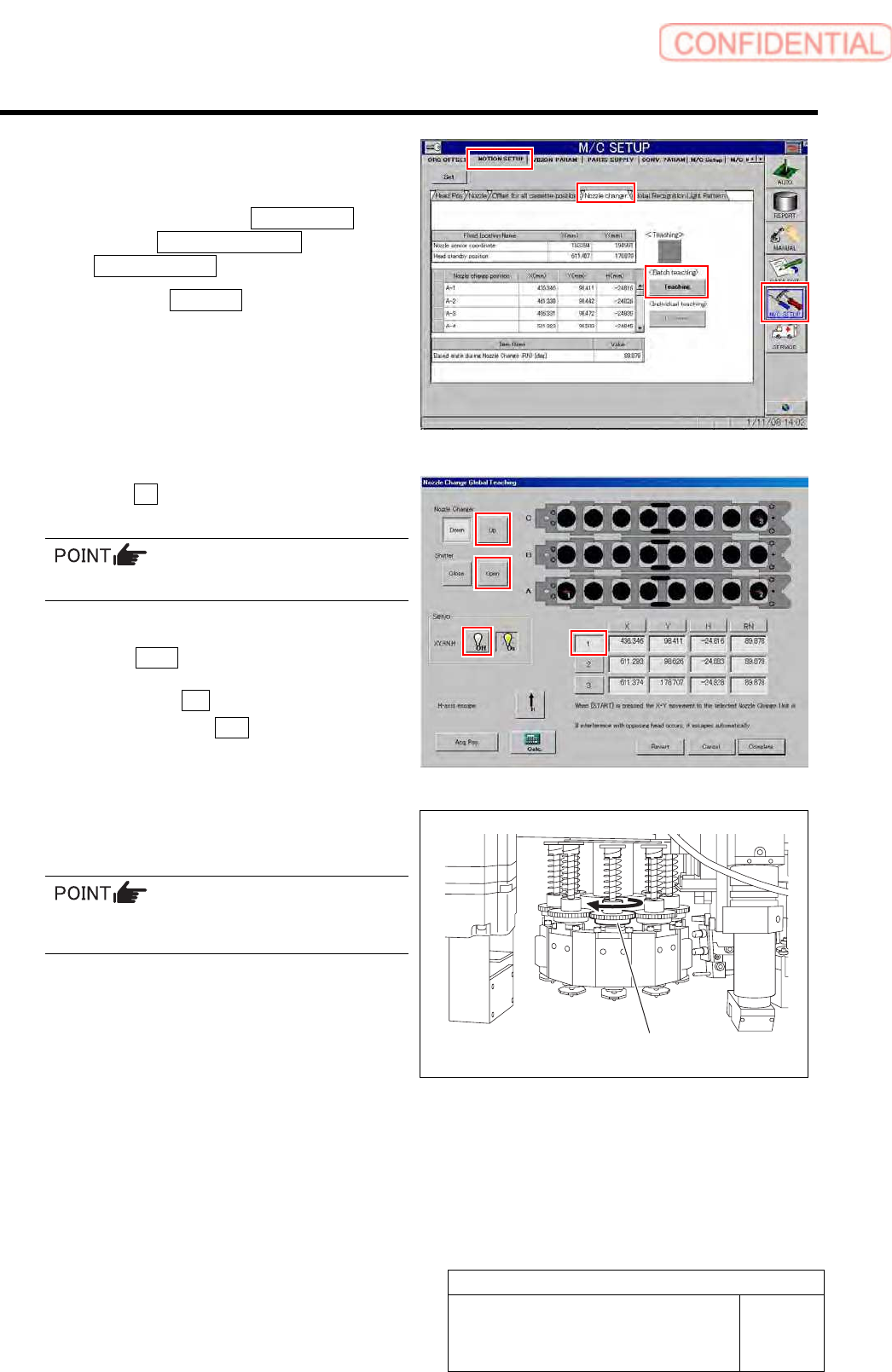
7 Display a Nozzle Changer Global Teaching
screen.
1. Click in an order of M/C SETUP
menuMOTION SETUP tab
Nozzle changer tab.
2. Click the Teaching button of <Batch
teaching>.
Nozzle Changer Global Teaching screen is
displayed.
8 Click the Up button for the nozzle changer to
raise the nozzle changer.
Make sure the pickup check camera moves up.
9 Click the Open button to open the shutter.
10 Make sure the 1 button is pressed, and
then turn the Servo OFF.
11 Turn the small gear clockwise by 90
degrees.
When the small gear is turned, the notch of the
jig nozzle faces inward of the system.
Small gear
Calibration
HLGB-10307-01
Nozzle Changer Teaching
SHEET
4/5
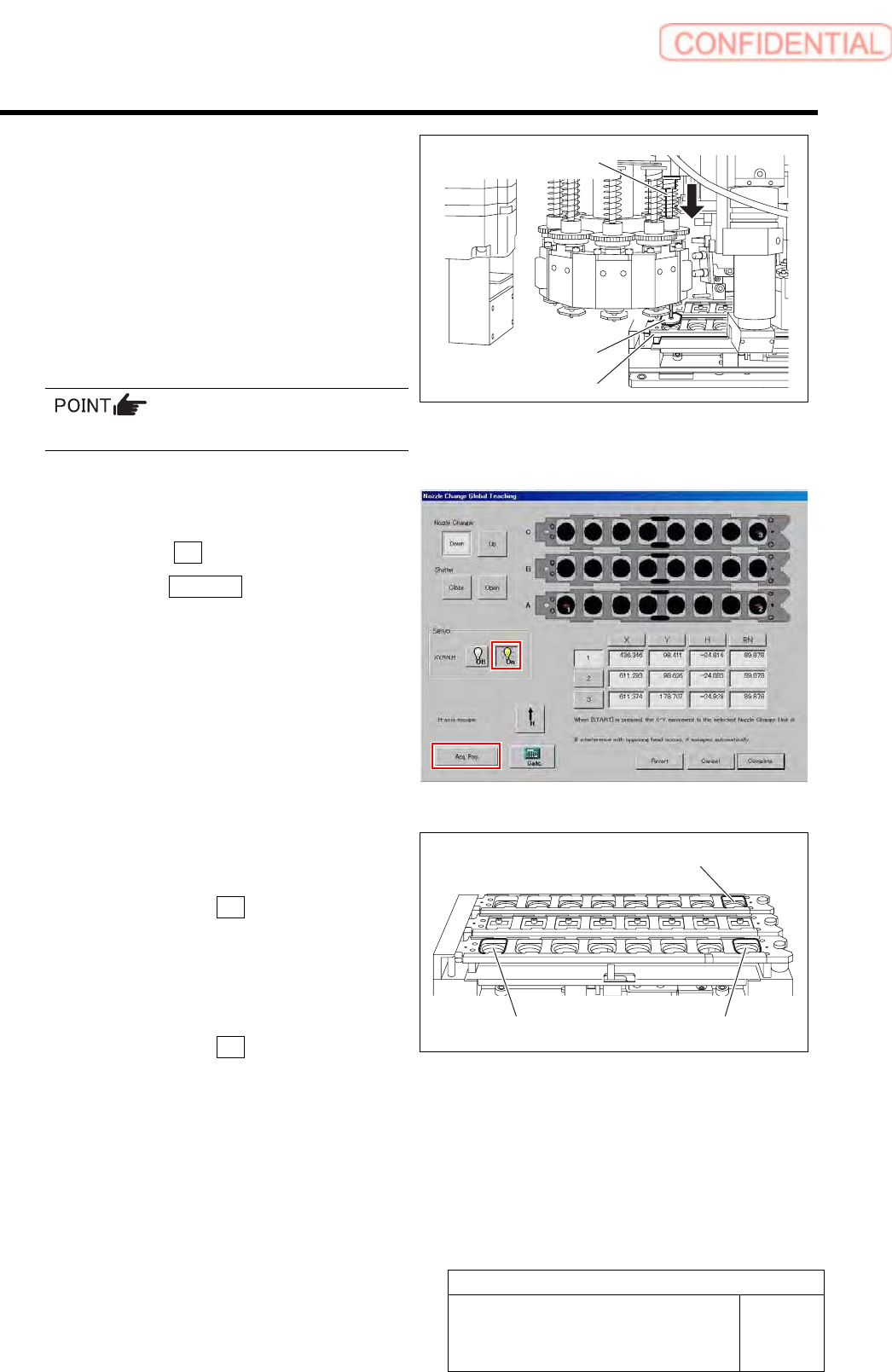
12 Capture coordinate of nozzle replacing
position.
1. Move the head manually so that the
jig nozzle of turret No.1 comes above
A-1 of the nozzle changer.
2. Lower the inner shaft with your finger
and make sure the jig nozzle can be
inserted into the nozzle cartridge A-1
smoothly.
Position the X, Y, and RN axes accurately.
3. While keeping the H-axis in the
lowered position with your finger, turn
the Servo ON.
4. Click the Acq. Pos. button.
13 In a like manner, acquire the coordination of
the nozzle positions for A-8 and C-8.
1. Make sure the 2 button is pressed,
and then turn the Servo OFF.
2. Capture A-8 replacing position
coordinate by the same procedure as
the procedure 12.
3. Make sure the 3 button is pressed,
and then turn the Servo OFF.
4. Capture C-8 replacing position
coordinate by the same procedure as
the procedure 12.
Inner shaft
Jig nozzle
Nozzle cartridge
C-8
A-8
A
-1