MAN00000772_SI-G200BB_SVCPDFA.pdf - 第23页
Wo rk Proce du re WKG B-10 1 02 - 01 G200 BB Hea d Mai n te nan ce SHEET 9/1 1 10 Att ach the outer collar and se cure the spline nut. 1. Making sure that the set shoe is in the correct position and orien tation, ins ta …
Work Procedure
WKGB-10102-01
G200BB Head Maintenance
SHEET
8/11
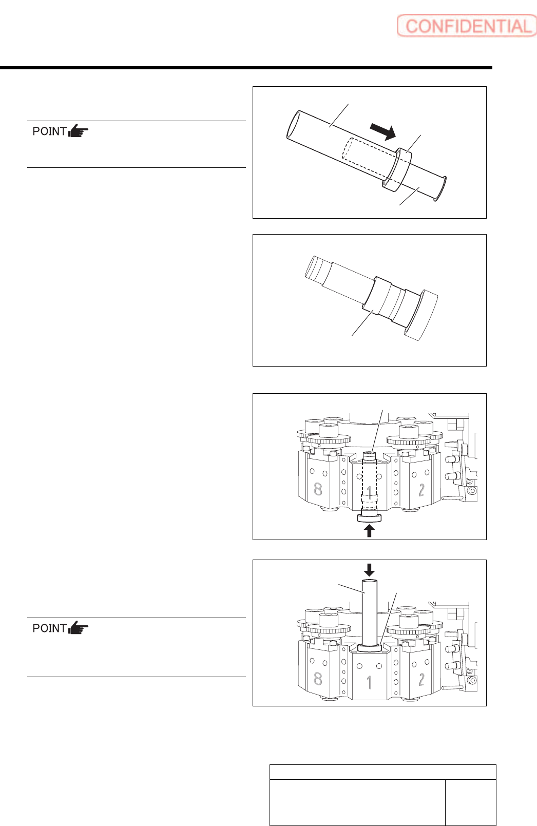
6 Using the bearing press fitting jig, press the
bearing into the spline nut.
Do not touch the end plate (black part) on top of
the spline nut.
7 Install the collar to the spline nut.
8 Insert the spline nut from the bottom side of
the head.
9 Using the bearing press fitting jig, press the
bearing into the head from the top side of
the head.
After attaching the bearing, rotate the spline
nut slowly to make sure that the spline nut
turns smoothly.
Bearing press fitting jig
Bearing
Spline nut
Collar
Spline nut
Bearing press
fitting jig
Spline nut
Work Procedure
WKGB-10102-01
G200BB Head Maintenance
SHEET
9/11
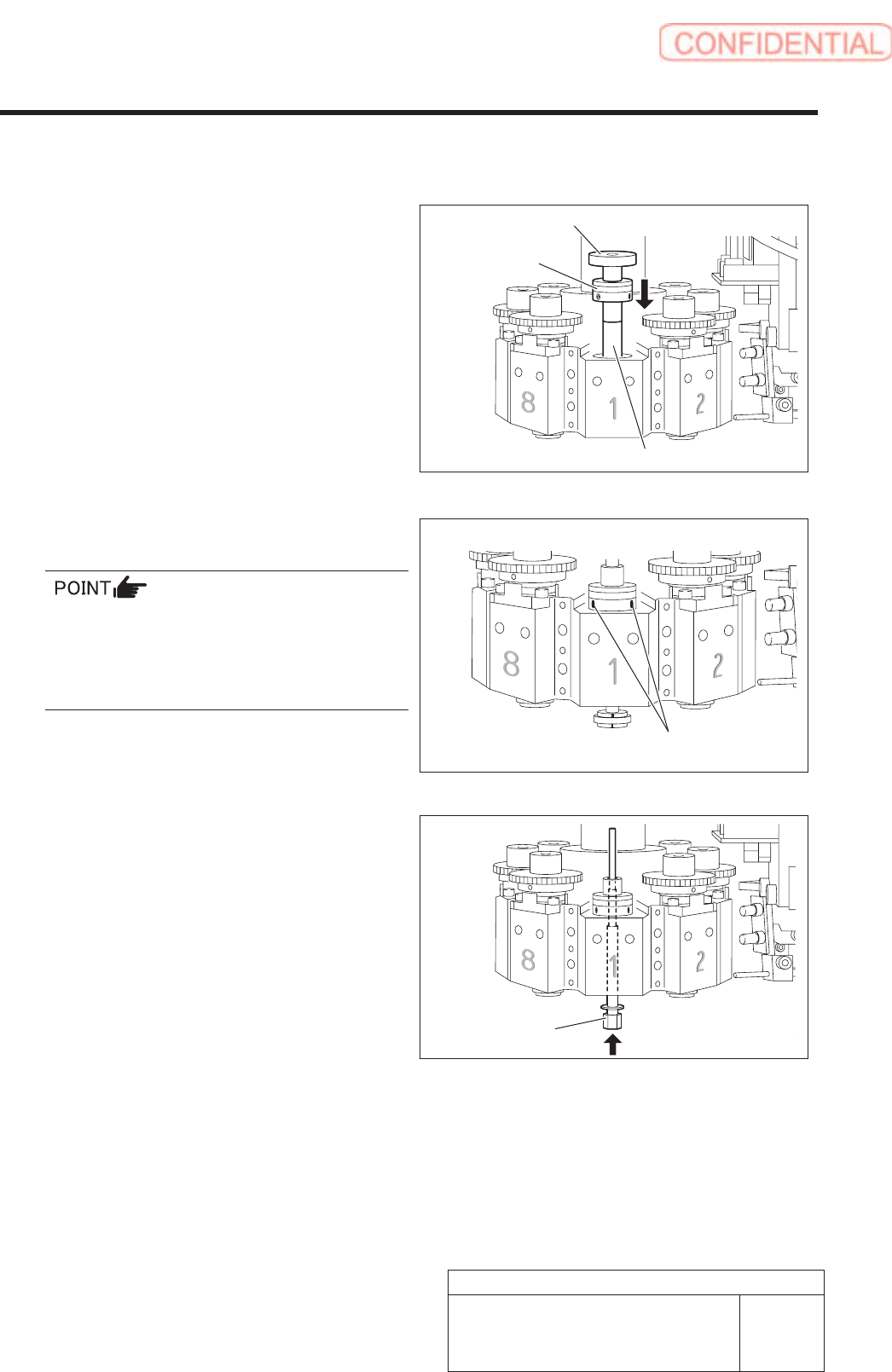
10 Attach the outer collar and secure the spline
nut.
1. Making sure that the set shoe is in the
correct position and orientation,
install the outer collar to the pulling
jig.
2. Place the pulling jig on the top of the
spline nut, and then pull the outer
collar down gently.
3. Remove the pulling jig from the top of
the spline nut.
Set the outer collar position to cover on
the spline nut upper marks.
The set screws should be tightened according to
mark number of spline nut. Take memo the prior
mark position before covering. Use inner spline
4. Remove an inner spline from a spline
nut and insert the spline nut assembling
Spline nut
Pulling jig
Outer collar
spline nut
assembling jig (1)
Set screw
for spline nut positioning to prevent from any
stress on the plastic parts of spline nut.
jig (1) from the bottom side of the spline
nut.
Work Procedure
WKGB-10102-01
G200BB Head Maintenance
SHEET
10/11
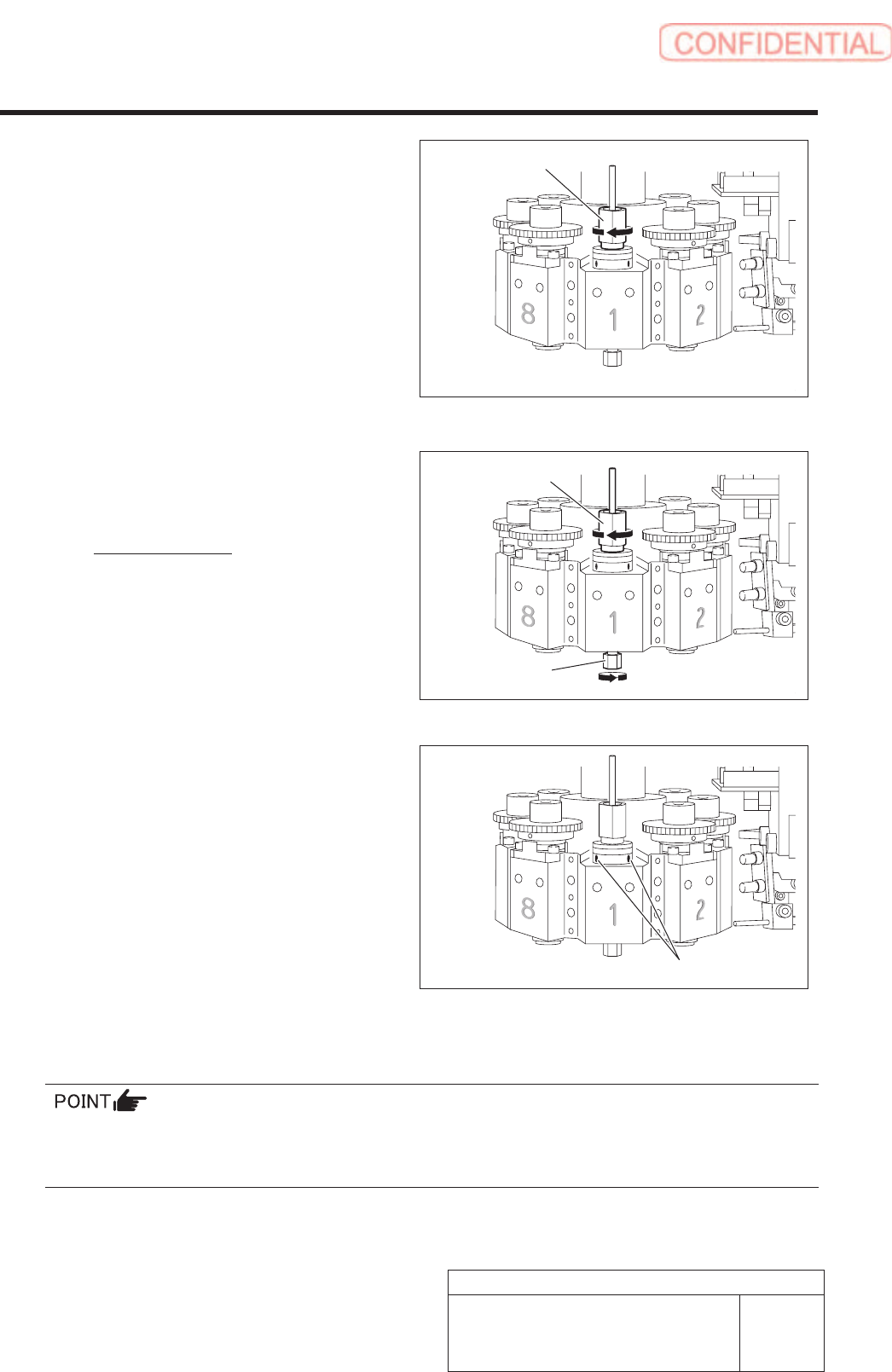
5. Apply the spline nut assembling jig (2)
to the spline nut from the top, and
then lightly tighten the spline nut
until the nut does not turn further.
6. Give preload with using the spline nut
assembling jig (1) and (2).
Preload: 6[cN・m]
7. Tighen two screws (H2.5 x 2.5) of outer
collar with 10[cNm] under preload
according to the mark on the spline nut.
8. Remove the spline nut assembling jig (2), and then remove the spline nut assembling jig
(1).
Insert the inner shaft and make sure the shaft moves up/down and rotates smoothly.
If you feel anomalies in up/down movement of the inner shaft, misalign the phases of the spline nut and
the outer collar purposely to find the orientation where the inner shaft moves up/down smoothly.
Spline nut assembling jig (2)
Spline nut
assembling jig (2)
Spline nut
assembling jig (1)
Set screw