MAN00000772_SI-G200BB_SVCPDFA.pdf - 第235页
Calibration HLGB-10308-01 Pickup Check Camera Calibration SHEET 5/5 13 Remove the l ength reference nozzle jig and press the [ST ART] button on the operation pane l. The message screen closes and returns to the Pickup Ca…
Calibration
HLGB-10308-01
Pickup Check Camera Calibration
SHEET
4/5
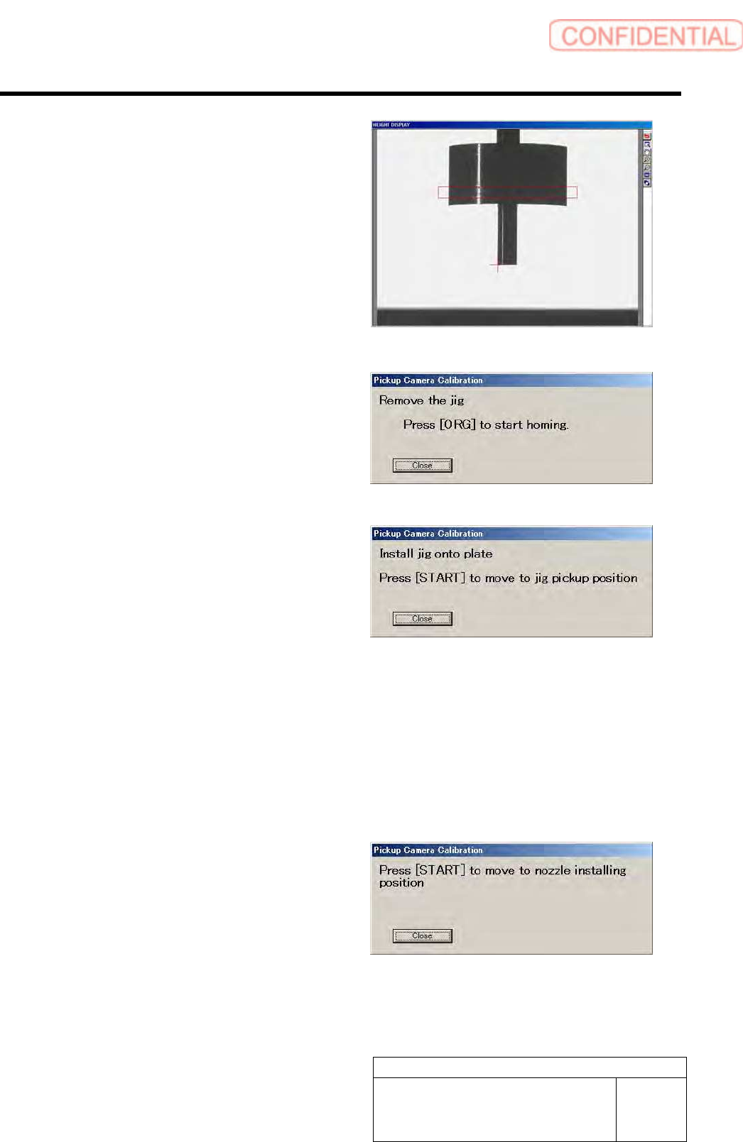
Check that the detection resolution check jig is
displayed on the HEIGHT DISPLAY at this time.
When measurement of the detection resolution check
jig is ended, the head moves to the supply section.
10 Remove the detection resolution check jig
from the nozzle and press the [ORG] button
on the operation panel.
Origin position return is performed and “Install jig
onto plate” is displayed on the message screen.
11 Continuously, make a second jig
measurement.
1. Again set the pickup check resolution
inspection jig onto the calibration
plate jig and press the [START] button
on the operation panel.
The length reference nozzle jig moves to the
measuring position and “Press [START] to start
nozzle measurement” is displayed on the
message screen.
2. Perform operations from nozzle
recognition to jig measurement
similarly to the procedure 8 to 9.
12 When the second measurement is ended,
press the [START] button to move the head
to nozzle installing position.
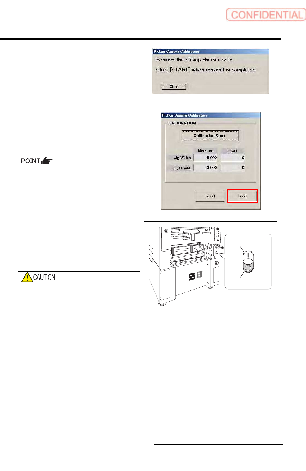
Turret No.1 moves to the nozzle installing position
and “Remove the pickup check nozzle” is displayed
on the message screen.
Calibration
HLGB-10308-01
Pickup Check Camera Calibration
SHEET
5/5
13 Remove the length reference nozzle jig and
press the [START] button on the operation
panel.
The message screen closes and returns to the Pickup
Camera Calibration screen.
14 Click the Save button on the Pickup Camera
Calibration screen.
Calibration information is saved and the Pickup
Camera Calibration screen closes.
In order to store the calibration result in the
unit, be sure to re-start the unit before
operating the unit.
15 Re-start the unit.
1. Close the Calibration screen.
2. Press the power off switch.
Shutting down of the system starts and the power
is automatically shut off.
Do not shut down the power from the start
menu of Windows
®
.
3. Press the power on switch.
The unit starts in a state that the pickup camera
calibration result is reflected on the system.
Power off switch
Power on switch
Calibration
HLGB-10309-01
Calibration Data Edit
SHEET
1/4
Calibration Data Edit
When revising the parts fitting position without performing calibration, edit the calibration data
according to the following procedure.
[Procedure]
1 Prepare a file of CSV format for correction in advance according to working which you want to
correct.
File can be arbitrarily named. The extension is “.csv”.
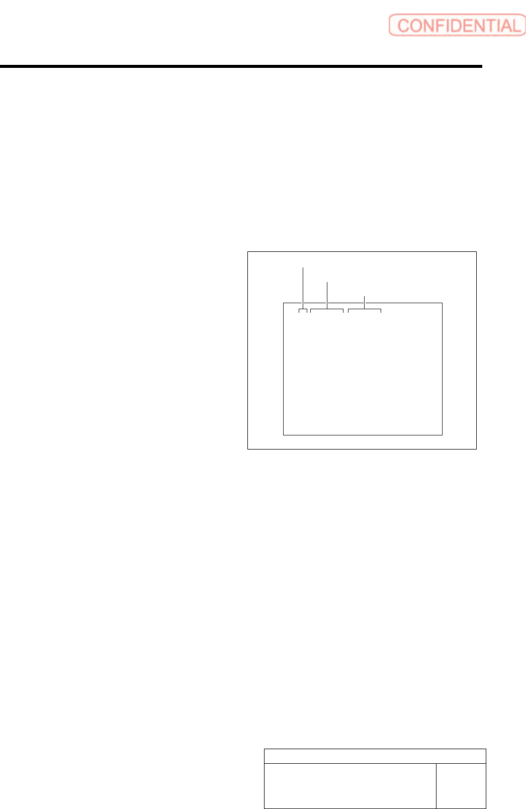
Format of CSV file for rotation center
correction
1. “1 to 8” on the left row are Index No.
2. Input correction amount in X direction
into the middle row.
・ When the fitting result in 180 degree deviates
to the left against the fitting result in 0 degree,
input half of the deviated amount with
positive sign.
・ When the fitting result in 180 degree deviates
to the right against the fitting result in 0
degree, input half of the deviated amount with
negative sign.
3. Input correction amount in Y direction
into the right row.
・ When the fitting result in 180 degree deviates
to the upper against the fitting result in 0
degree, input half of the deviated amount with
positive sign.
・ When the fitting result in 180 degree deviates
to the lower against the fitting result in 0
degree, input half of the deviated amount with
negative sign.
1,0.000,0.000
2,0.000,0.000
3,0.000,0.000
4,0.000,0.000
5,0.000,0.000
6,0.000,0.000
7,0.000,0.000
8,0.000,0.000
Index No.
Correction value in X direction
Correction value in Y direction