MAN00000772_SI-G200BB_SVCPDFA.pdf - 第239页
Calibration HLGB-10309-01 Calibration Data Edit SHEET 4/4 4 Display a Calibration Dat a Edit screen. 1. Click the Cal ibration Data Ed it button on the CALIBRA TION screen. Calibration Data Edi t screen is displayed. 5 C…
Calibration
HLGB-10309-01
Calibration Data Edit
SHEET
3/4
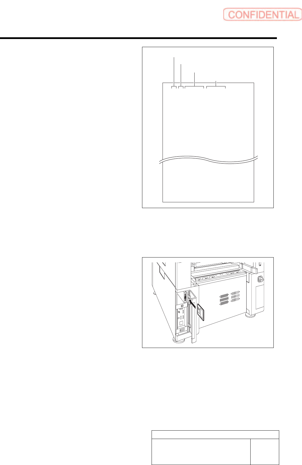
Format of CSV file for transcription correction
in every angle
5. “1 to 8” on the left row are Index No.
6. Input transcription angle into the
second row from the left.
Input four kinds of transcription angles, 0 degree,
90 degrees, 180 degrees and 270 degrees to one
Index No.
7. Input correction amount in X direction
in the third row from the left.
・ When attempting to correct the fitting
position to the right side (+X direction), input
a value with positive sign.
・ When attempting to correct the fitting
position to the left side (-X direction), input
a value with negative sign.
8. Input correction amount in Y direction
in the third row from the left.
・ When attempting to correct the fitting
position to the right side (+Y direction), input
a value with positive sign.
・ When attempting to correct the fitting
position to the left side (-Y direction), input
a value with negative sign.
1,0,0.000,0.000
1,90,0.000,0.000
1,180,0.000,0.000
1,270,0.000,0.000
2,0,0.000,0.000
2,90,0.000,0.000
2,180,0.000,0.000
2,270,0.000,0.000
8,0,0.000,0.000
8,90,0.000,0.000
8,180,0.000,0.000
8,270,0.000,0.000
2 Save the created CSV file for correction to a
floppy disk.
3 Set the floppy disk which contains the CSV
file for correction to the unit.
Index No.
Transcription angle
Correction value in X direction
Correction value in Y direction
Calibration
HLGB-10309-01
Calibration Data Edit
SHEET
4/4
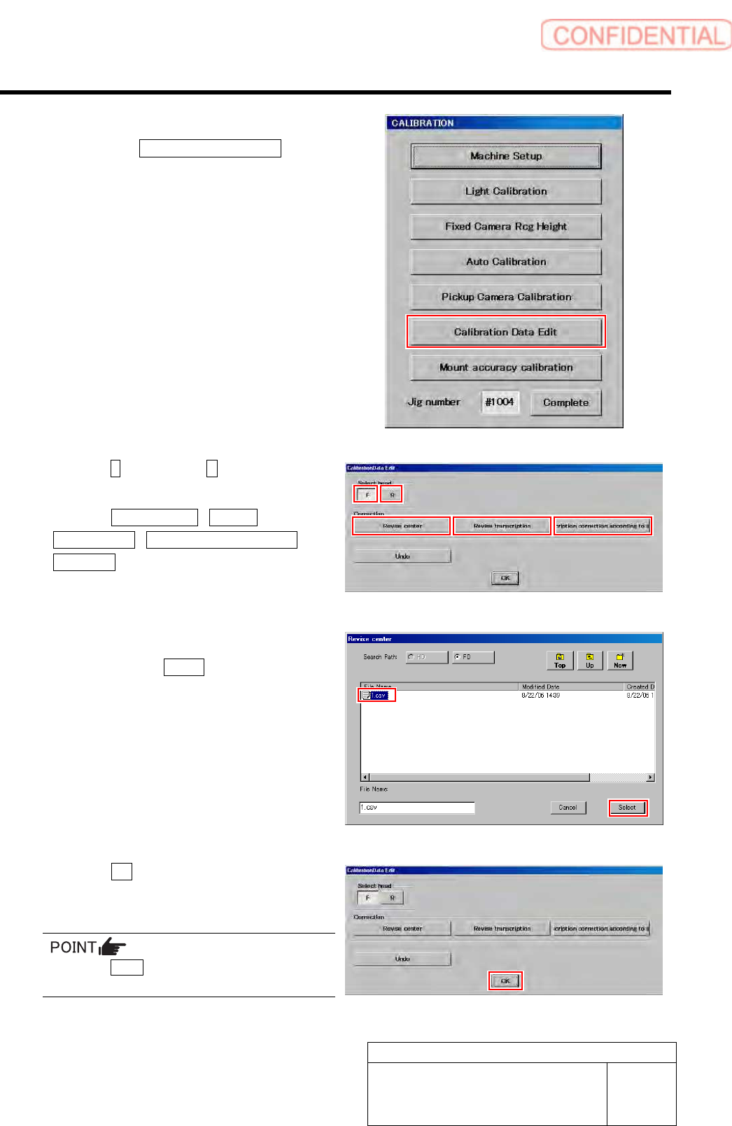
4 Display a Calibration Data Edit screen.
1. Click the Calibration Data Edit button
on the CALIBRATION screen.
Calibration Data Edit screen is displayed.
5 Click the F button or the R button to select a
head to be corrected.
6 Click the Revise center / Revise
Transcription / Transcription correction
according button to select working which
you attempt to correct.
Correction file select screen is displayed.
7 Select a correction file included in the floppy
disk and click the Select button.
Correction file is selected, and the file select screen
closes.
The right screen is an example of file select screen for
rotation center correction.
8 Click the OK button.
The offset value is saved, and the calibration edit
screen closes.
Press the Undo button, then you can return to
previous one calibration data.
Calibration
HLGB-10310-01
Fixed Camera Rcg Height Calibration
SHEET
1/5
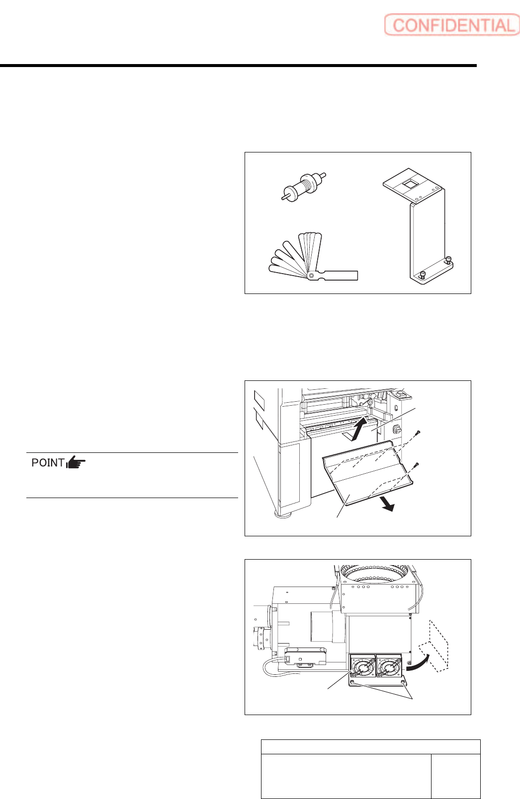
Fixed Camera Rcg Height Calibration
[Necessary jigs]
A Length reference nozzle jig
B Fixed camera jig base
C Thickness gauge (t=0.03 mm)
[Procedure]
1 Press the emergency stop switch to turn off the servo.
2 Turn off the interlock switch and open the door.
3 Remove the lower cover and shooter on
front and rear of the unit.
1. Loosen screw (2-+T4x8) to remove the
lower cover.
Tile the lower cover slightly toward you and pull
the fan cable to remove the lower panel.
2. Loosen screw (2-+T4x8) to remove the
shooter.
4 Loosen cap screws (2-CP5x10) fixing the
fixed camera cooling fan to remove the fan.
Temporarily place the removed fan on the side of the
fixed camera.
A
B
C
Cap screw
Cooling fan
Lower cover
Shooter